Nissan Qashqai (2007-2010). Manual — part 946
HAC-144
< FUNCTION DIAGNOSIS >
[MANUAL AIR CONDITIONER]
BLOWER MOTOR CONTROL SYSTEM
BLOWER MOTOR CONTROL SYSTEM
Description
INFOID:0000000001069953
SYSTEM DESCRIPTION
Component Parts
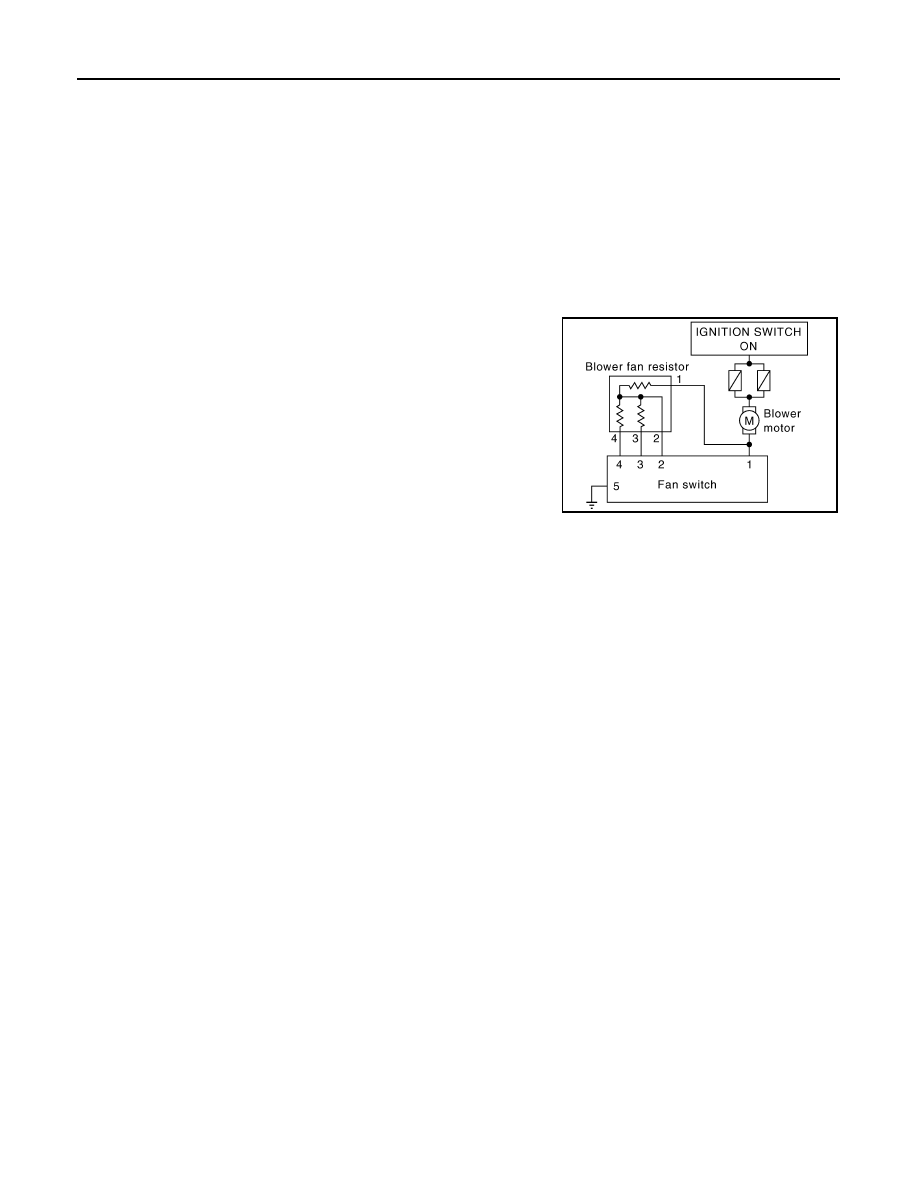
Blower motor control system components are:
• Blower motor
• Blower fan resistor
• Heater control panel (Fan switch)
Blower motor circuit
The blower speed is selected manually (1st – 4th) by the fan switch.
JPIIA0102GB

MAGNET CLUTCH CONTROL SYSTEM
HAC-145
< FUNCTION DIAGNOSIS >
[MANUAL AIR CONDITIONER]
C
D
E
F
G
H
J
K
L
M
A
B
HAC
N
O
P
MAGNET CLUTCH CONTROL SYSTEM
Description
INFOID:0000000001069955
SYSTEM DISCRIPTION
• When A/C switch of the heater control panel is turned ON, the compressor ON signal is input to BCM.
• BCM transmits the compressor ON signal to ECM via CAN communication.
• ECM judges the condition of each sensor (Refrigerant pressure sensor signal, accelerator position signal,
etc.), and transmits the compressor ON signal to IPDM E/R via CAN communication.
• IPDM E/R receives the compressor ON signal from ECM, turns the A/C relay ON, and activates the com-
pressor.
Magnet Clutch Circuit
COMPRESSOR PROTECTION CONTROL
When the high-pressure side detected by the refrigerant pressure sensor is either approx. 2.7 MPa (approx.
27.5 kg/cm
2
·G) or more, or approx. 0.14 MPa (approx. 1.4 kg/cm
2
·G) or less, ECM turns the A/C relay OFF
and stops the compressor.
JSIIA0288GB
HAC-146
< FUNCTION DIAGNOSIS >
[MANUAL AIR CONDITIONER]
PTC HEATER CONTROL SYSTEM
PTC HEATER CONTROL SYSTEM
Description
INFOID:0000000001117103
SYSTEM DESCRIPTION
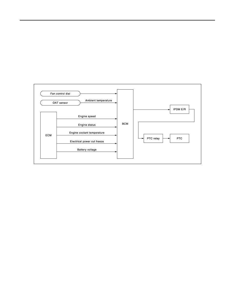
BCM controls PTC (Positive Temperature Coefficient) heater correspond to fan ON signal, ambient tempera-
ture, engine coolant temperature, engine speed, engine status, electrical power cut freeze signal and battery
voltage.
BCM sends PTC ON signal to IPDM E/R, via CAN communication.
BCM judges whether PTC can be turned ON, based on each sensor status (ambient temperature, engine
speed, engine coolant temperature, etc.). If it judges PTC can be turned ON, it send PTC heater relay ON sig-
nal to IPDM E/R via CAN communication.
System Operation
JSIIA0292GB

HIGH-LEVEL VENTILATOR DOOR MOTOR
HAC-147
< COMPONENT DIAGNOSIS >
[MANUAL AIR CONDITIONER]
C
D
E
F
G
H
J
K
L
M
A
B
HAC
N
O
P
COMPONENT DIAGNOSIS
HIGH-LEVEL VENTILATOR DOOR MOTOR
Description
INFOID:0000000001070082
COMPONENT DESCRIPTION
High-level Ventilator Door Motor
The high-level ventilator door motor (1) are attached to the A/C unit assembly. It rotates so that air is dis-
charged from the outlet set by the high-level ventilator switch. Motor rotation is conveyed to a link which acti-
vates the high-level ventilator door.
LHD models
RHD models
Component Function Check
INFOID:0000000001070083
1.
CONFIRM SYMPTOM BY PERFORMING THE FOLLOWING OPERATIONAL CHECK
1.
Press high-level ventilator switch. High-level ventilator switch indicator should illuminate.
2.
Press high-level ventilator switch again. High-level ventilator indicator should not illuminate.
3.
Confirm that discharge air comes out.
Is the inspection result normal?
YES
>> END.
NO
>> Go to diagnosis procedure. Refer to
HAC-147, "Diagnosis Procedure"
.
Diagnosis Procedure
INFOID:0000000001070084
1.
CHECK HIGH-LEVEL VENTILATOR DOOR CONTROL LINKAGE
Check high-level ventilator door control linkage.
Is it installed normally?
YES
>> GO TO 2.
NO
>> Repair or adjust control linkage.
2.
CHECK POWER SUPPLY FOR HEATER CONTROL PANEL
1.
Disconnect heater control panel connector.
:
Vehicle front
JPIIA0024ZZ
:
Vehicle front
JPIIA0025ZZ
Нет комментариевНе стесняйтесь поделиться с нами вашим ценным мнением.
Текст