Nissan Qashqai (2007-2010). Manual — part 945

HAC-140
< FUNCTION DIAGNOSIS >
[MANUAL AIR CONDITIONER]
DIAGNOSIS SYSTEM (BCM)
DIAGNOSIS SYSTEM (BCM)
COMMON ITEM
COMMON ITEM : CONSULT-III Function (BCM - COMMON ITEM)
INFOID:0000000001096703
APPLICATION ITEM
CONSULT-III performs the following functions via CAN communication with BCM.
SYSTEM APPLICATION
BCM can perform the following functions for each system.
NOTE:
It can perform the diagnosis modes except the following for all sub system selection items.
AIR CONDITIONER
AIR CONDITIONER : CONSULT-III Function (BCM - MANUAL AIR CONDITIONER)
INFOID:0000000001096704
DATA MONITOR
Diagnosis mode
Function Description
WORK SUPPORT
Changes the setting for each system function.
SELF-DIAG RESULTS
Displays the diagnosis results judged by BCM. Refer to
CAN DIAG SUPPORT MNTR
Monitors the reception status of CAN communication viewed from BCM.
DATA MONITOR
The BCM input/output signals are displayed.
ACTIVE TEST
The signals used to activate each device are forcibly supplied from BCM.
ECU IDENTIFICATION
The BCM part number is displayed.
CONFIGURATION
• Enables to read and save the vehicle specification.
• Enables to write the vehicle specification when replacing BCM.
System
Sub system selection item
Diagnosis mode
WORK SUPPORT
DATA MONITOR
ACTIVE TEST
—
BCM
×
Door lock
DOOR LOCK
×
×
×
Rear window defogger
REAR DEFOGGER
×
×
Warning chime
BUZZER
×
×
Interior room lamp timer
INT LAMP
×
×
×
Remote keyless entry system
MULTI REMOTE ENT
×
×
×
Exterior lamp
HEAD LAMP
×
×
×
Wiper and washer
WIPER
×
×
×
Turn signal and hazard warning lamps
FLASHER
×
×
Air conditioner
AIR CONDITONER
×
Intelligent Key system
INTELLIGENT KEY
×
Combination switch
COMB SW
×
Immobilizer
IMMU
×
×
Interior room lamp battery saver
BATTERY SAVER
×
×
×
Trunk open
TRUNK
×
Vehicle security system
THEFT ALM
×
×
×
Signal buffer system
SIGNAL BUFFER
×
×
PTC heater system
PTC HEATER
×
×

DIAGNOSIS SYSTEM (BCM)
HAC-141
< FUNCTION DIAGNOSIS >
[MANUAL AIR CONDITIONER]
C
D
E
F
G
H
J
K
L
M
A
B
HAC
N
O
P
Display item list
PTC HEATER
PTC HEATER : CONSULT-III Function (BCM - PTC HEATER)
INFOID:0000000001114917
DATA MONITOR
Display Item List
ACTIVE TEST
Test item
Monitor item [unit]
Contents
IGN ON SW
“On/Off”
Displays “IGN position (On)/OFF, ACC position (Off)” status as judged from ignition switch sig-
nal.
FAN ON SIG
“On/Off”
Displays “FAN (On)/FAN (Off)” status as judged from blower fan motor switch signal.
AIR COND SW
“On/Off”
Displays “COMP (On)/COMP (Off)” status as judged from A/C switch signal.
Monitor Item
[Unit]
Description
ELEC PWR CUT
[OFF/FREEZ/INHBT]
Indicate [OFF/FREEZ/INHBT] condition of the PTC heater states.
FAN ON SIG
[On/Off]
Displays [FAN (ON)/FAN (OFF)] status as judged from blower fan motor signal.
ENGINE STATUS
[STOP/STAL/RUN/CRA]
Indicate [STOP/STALL/RUN/CRA] condition of the engine states.
ENG COOLNT T
[
°
C]
The engine coolant temperature (determined by the signal voltage of the engine coolant tem-
perature sensor) is displayed.
BATTERY VOLT
[V]
The power supply voltage of BCM is displayed.
ENGINE RPM
[rpm]
Indicates the engine speed computed from the signal of the crankshaft position sensor.
OUTSIDE TEMP
[
°
C]
The outside air temperature (determined by the signal voltage of the OAT sensor) is displayed.
Test Item
Operation
Description
PTC HEATER
OFF
PTC 1
PTC 2
PTC 3
This test is able to check PTC heater operation.

HAC-142
< FUNCTION DIAGNOSIS >
[MANUAL AIR CONDITIONER]
HIGH-LEVEL VENTILATOR DOOR CONTROL SYSTEM
HIGH-LEVEL VENTILATOR DOOR CONTROL SYSTEM
Description
INFOID:0000000001069949
SYSTEM DESCRIPTION
Component Parts
High-level ventilator door control system components are:
• Heater control panel (High-level ventilator switch)
• High-level ventilator door motor
High-level ventilator door motor circuit
JPIIA0176GB
INTAKE DOOR CONTROL SYSTEM
HAC-143
< FUNCTION DIAGNOSIS >
[MANUAL AIR CONDITIONER]
C
D
E
F
G
H
J
K
L
M
A
B
HAC
N
O
P
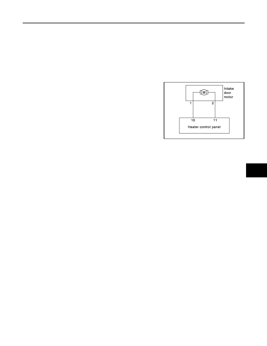
INTAKE DOOR CONTROL SYSTEM
Description
INFOID:0000000001069952
SYSTEM DESCRIPTION
Component Parts
Intake door control system components are:
• Heater control panel (REC switch)
• Intake door motor
Intake door motor circuit
JPIIA0175GB
Нет комментариевНе стесняйтесь поделиться с нами вашим ценным мнением.
Текст