Nissan Qashqai (2007-2010). Manual — part 34

EM-84
< REMOVAL AND INSTALLATION >
[HR16DE]
ENGINE ASSEMBLY
• Use either 2-pole lift type or separate type lift as best you can. If board-on type is used for unavoid-
able reasons, support at the rear axle jacking point with a transmission jack or similar tool before
starting work, in preparation for the backward shift of center of gravity.
• For supporting points for lifting and jacking point at rear axle, refer to
REMOVAL
Outline
Remove the engine and the transaxle assembly from the vehicle downward. Separate the engine and the tran-
saxle.
Preparation
1.
Release fuel pressure. Refer to
.
2.
Drain engine coolant from radiator. Refer to
.
CAUTION:
• Perform this step when the engine is cold.
• Never spill engine coolant on drive belt.
3.
Remove the following parts.
• Engine undercover
• Front fender protector (RH and LH): Refer to
• Front road wheels and tires: Refer to
.
• Battery and battery tray: Refer to
.
• Drive belt: Refer to
EM-16, "Removal and Installation"
• Air duct and air cleaner case assembly: Refer to
.
• Radiator hose (upper and lower): Refer to
• Exhaust front tube: Refer to
.
Engine Room LH
1.
Disconnect all connections of engine harness around the engine mounting insulator (LH), and then tem-
porarily secure the engine harness into the engine side.
CAUTION:
Protect connectors using a resin bag against foreign materials.
2.
Disconnect fuel feed hose at engine side. Refer to
.
3.
Disconnect heater hoses, and install plugs them to prevent engine coolant from draining. Refer to
4.
Disconnect control linkage from transaxle. Refer to
5.
Remove ground cable at transaxle side.
Engine Room RH
1.
Remove ground cable between front cover and vehicle.
2.
Alternator and alternator bracket; Refer to
CHG-25, "HR16DE MODELS : Exploded View"
3.
Disconnect reservoir tank hose. Refer to
4.
Remove A/C compressor with piping connected from the engine. Temporarily secure it on the vehicle side
with a rope to avoid putting load on it. (with A/C models) Refer to
Vehicle Underbody
1.
Remove front wheel sensor (LH and RH) for ABS from steering knuckle. Refer to
2.
Remove brake caliper assembly with piping connected from steering knuckle. Temporarily secure it on the
vehicle side with a rope to avoid load on it. Refer to
BR-37, "BRAKE CALIPER ASSEMBLY : Exploded
.
3.
Remove stabilizer connecting rod. Refer to
.
4.
Remove steering knuckle mounting nuts and bolts. Refer to
.
5.
Disconnect steering outer socket. Refer to
.
6.
Remove drive shafts (LH and RH) and center bearing cover bracket. Refer to
7.
Disconnect steering lower joint at power steering gear assembly side, and release steering lower shaft.
Refer to
ENGINE ASSEMBLY
EM-85
< REMOVAL AND INSTALLATION >
[HR16DE]
C
D
E
F
G
H
I
J
K
L
M
A
EM
N
P
O
8.
Remove rear torque rod.
9.
Remove front suspension member. Refer to
10. Preparation for the separation work of transaxle is as follows:
• Remove transaxle joint bolts which pierce at oil pan (upper) lower rear side. Refer to
.
Removal
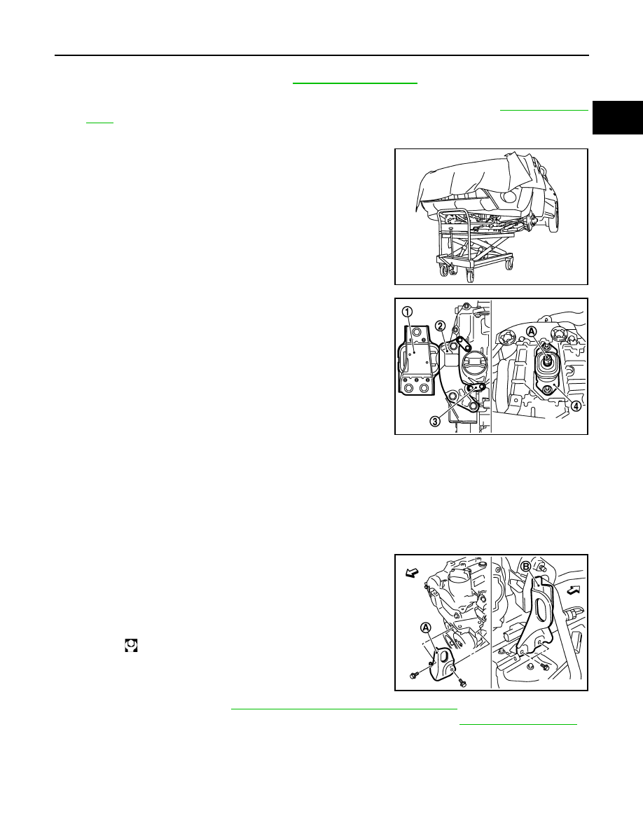
1.
Use a manual lift table caddy (commercial service tool) or equiv-
alently rigid tool such as a transmission jack. Securely support
bottom of the engine and the transaxle assembly.
CAUTION:
Put a piece of wood or something similar as the supporting
surface, secure a completely stable condition.
2.
Remove engine mounting insulator (RH) (1), engine mounting
bracket (RH) (2) and engine mounting stay (3).
3.
Remove engine mounting through bolt-securing nut (A).
4.
Carefully lower jack, or raise lift to remove the engine and the transaxle assembly.
CAUTION:
• Make sure that no part interferes with the vehicle side.
• Before and during this lifting, always check if any harnesses are left connected.
• During the removal, always be careful to prevent the vehicle from falling off the lift due to
changes in the center of gravity.
• If necessary, support the vehicle by setting jack or suitable tool at the rear.
Separation
1.
Install engine slinger to cylinder head front left side (A) and rear
right side (B).
2.
Remove starter motor. Refer to
STR-20, "HR16DE MODELS : Exploded View"
3.
Lift with a hoist and separate the engine from the transaxle assembly. Refer to
.
INSTALLATION
Note the following, and install in the reverse order of removal.
• Do not allow engine oil to get on engine mounting insulator. Be careful not to damage engine mounting insu-
lator.
• Make sure that each mounting insulator is seated properly, and tighten mounting nuts and bolts.
PBIC1190E
4
: Engine mounting insulator (LH)
JPBIA0512ZZ
: Engine front
Slinger bolts
: 25.5 N·m (2.6 kg-m, 19 ft-lb)
PBIC3738E
EM-86
< REMOVAL AND INSTALLATION >
[HR16DE]
ENGINE ASSEMBLY
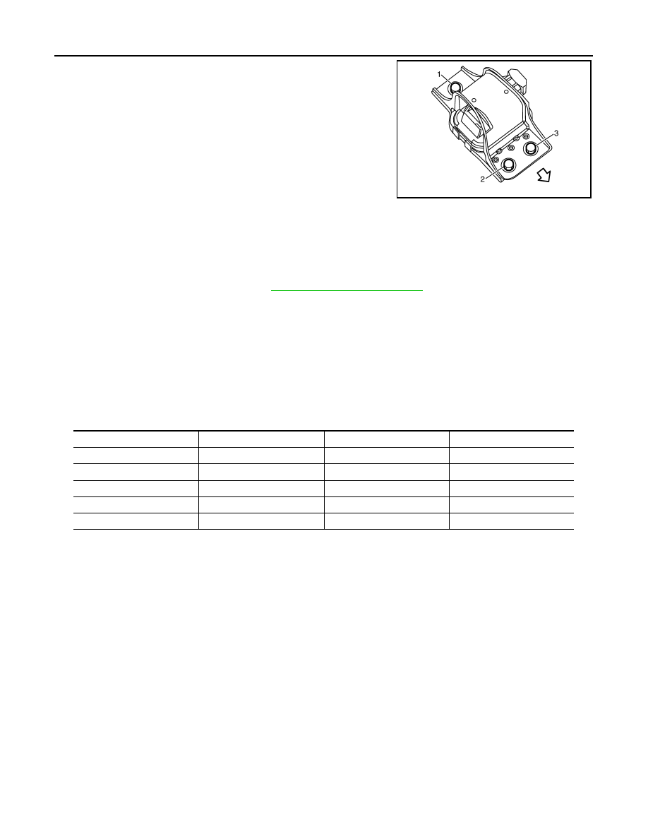
• Tighten engine mounting insulator (RH) bolts in the numerical
order shown in the figure.
Inspection
INFOID:0000000000893873
INSPECTION AFTER INSTALLATION
Inspection for Leaks
• Before starting engine, check oil/fluid levels including engine coolant and engine oil. If less than required
quantity, fill to the specified level. Refer to
MA-21, "Fluids and Lubricants"
.
• Use procedure below to check for fuel leakage.
- Turn ignition switch “ON” (with engine stopped). With fuel pressure applied to fuel piping, check for fuel leak-
age at connection points.
- Start engine. With engine speed increased, check again for fuel leakage at connection points.
• Run engine to check for unusual noise and vibration.
• Warm up engine thoroughly to make sure there is no leakage of fuel, exhaust gases, or any oil/fluids includ-
ing engine oil and engine coolant.
• Bleed air from lines and hoses of applicable lines, such as in cooling system.
• After cooling down engine, again check oil/fluid levels including engine oil and engine coolant. Refill to the
specified level, if necessary.
Summary of the inspection items:
*: Transmission/transaxle/CVT fluid, power steering fluid, brake fluid, etc.
: Vehicle front
JPBIA0280ZZ
Items
Before starting engine
Engine running
After engine stopped
Engine coolant
Level
Leakage
Level
Engine oil
Level
Leakage
Level
Other oils and fluid*
Level
Leakage
Level
Fuel
Leakage
Leakage
Leakage
Exhaust gases
—
Leakage
—
ENGINE STAND SETTING
EM-87
< DISASSEMBLY AND ASSEMBLY >
[HR16DE]
C
D
E
F
G
H
I
J
K
L
M
A
EM
N
P
O
DISASSEMBLY AND ASSEMBLY
ENGINE STAND SETTING
Setting
INFOID:0000000000893874
NOTE:
Explained here is how to disassemble with engine stand supporting transmission surface. When using differ-
ent type of engine stand, note with difference in steps and etc.
1.
Remove the engine and the transaxle assembly from the vehicle, and separate the transaxle from the
engine. Refer to
2.
Remove clutch cover and clutch disc. Refer to
CL-16, "HR16DE, MR20DE : Exploded View"
.
3.
Remove flywheel.
• Secure flywheel with a stopper plate [SST: KV11105210], and remove mounting bolts.
CAUTION:
• Never disassemble flywheel.
• Never place flywheel with signal plate facing down.
• When handling signal plate, take care not to damage or scratch it.
• Handle signal plate in a manner that prevents it from becoming magnetized.
4.
Lift the engine with a hoist to install it onto widely use engine stand.
CAUTION:
• Use the engine stand that has a load capacity [approximately 135 kg (298 lb) or more] large
enough for supporting the engine weight.
• If the load capacity of stand is not adequate, remove the following parts beforehand to reduce the poten-
tial risk of overturning stand.
- Intake manifold: Refer to
- Exhaust manifold: Refer to
- Rocker cover: Refer to
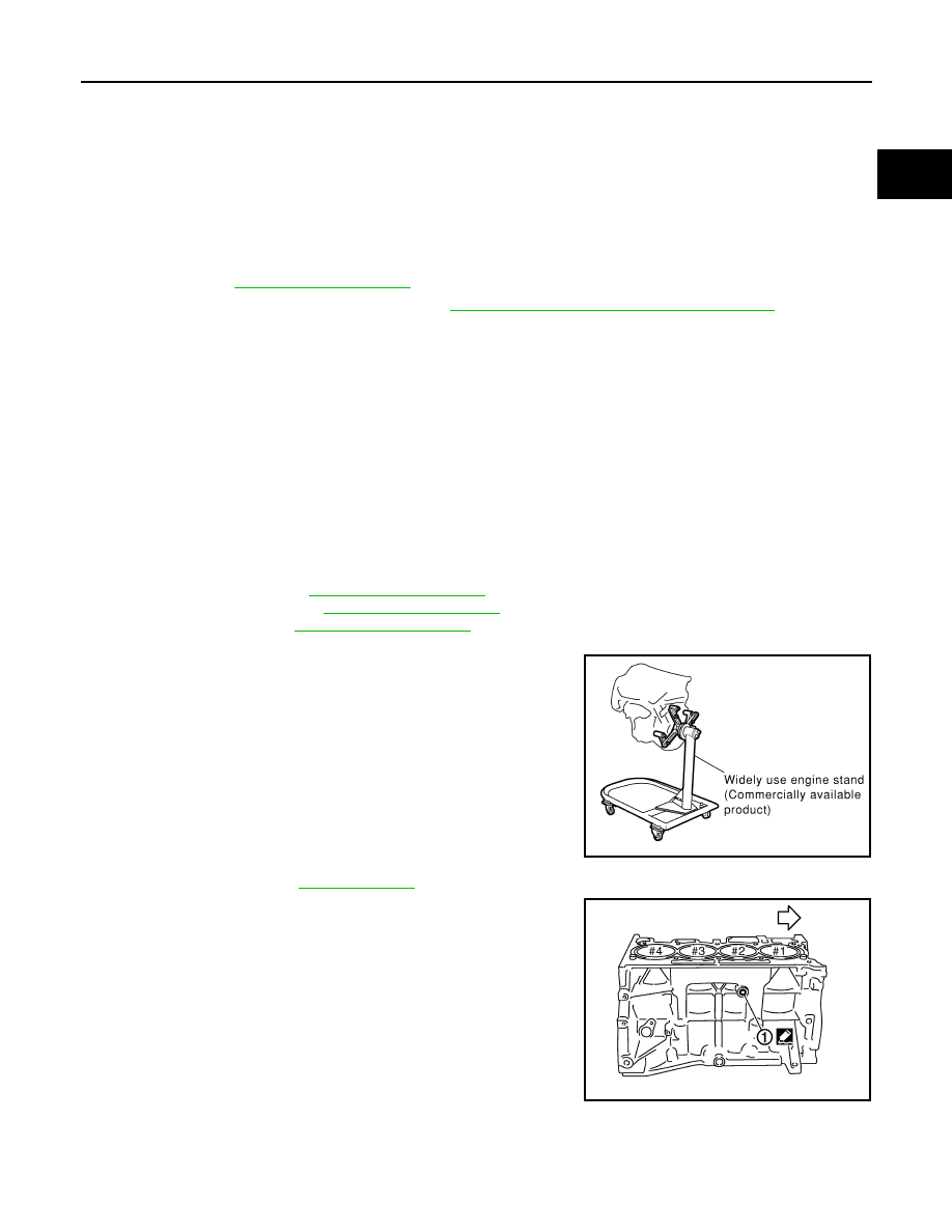
NOTE:
The figure shows an example of widely use engine stand that
can support mating surface of transaxle with flywheel removed.
CAUTION:
Before removing the hanging chains, make sure the engine
stand is stable and there is no risk of overturning.
5.
Drain engine oil. Refer to
.
6.
Drain engine coolant by removing water drain plug (1) from
inside of the engine.
Use Genuine Liquid Gasket or equivalent.
PBIC0085E
: Engine front
PBIC3742E
Нет комментариевНе стесняйтесь поделиться с нами вашим ценным мнением.
Текст