Nissan Qashqai (2007-2010). Manual — part 32
EM-76
< ON-VEHICLE REPAIR >
[HR16DE]
CYLINDER HEAD
c.
Completely loosen.
CAUTION:
In this step, loosen bolts in reverse order of that indicated in the figure.
d.
Tighten all bolts.
e.
Turn all bolts 75 degrees clockwise (angle tightening).
CAUTION:
Check and confirm the tightening angle by using the angle
wrench [SST: KV10112100] (A) or protractor. Avoid judg-
ment by visual inspection without the tool.
f.
Turn all bolts 75 degrees clockwise again (angle tightening).
3.
Install in the reverse order of removal, for the rest of parts.
Disassembly and Assembly
INFOID:0000000000894030
DISASSEMBLY
1.
Remove spark plug with a spark plug wrench (commercial service tool).
2.
Remove valve lifter.
• Identify installation positions, and store them without mixing them up.
3.
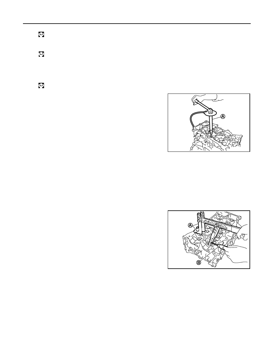
Remove valve collet.
• Compress valve spring with the valve spring compressor, the
attachment and the adapter [SST: KV10116200] (A). Remove
valve collet with a magnet hand (B).
CAUTION:
Be careful not to damage valve lifter holes.
4.
Remove valve spring retainer and valve spring.
5.
Push valve stem to combustion chamber side, and remove valve.
• Identify installation positions, and store them without mixing them up.
: 66.7 N·m (6.8 kg-m, 49 ft-lb)
: 0 N·m (0 kg-m, 0 ft-lb)
: 40.0 N·m (4.1 kg-m, 30 ft-lb)
PBIC3733E
PBIC3727E
CYLINDER HEAD
EM-77
< ON-VEHICLE REPAIR >
[HR16DE]
C
D
E
F
G
H
I
J
K
L
M
A
EM
N
P
O
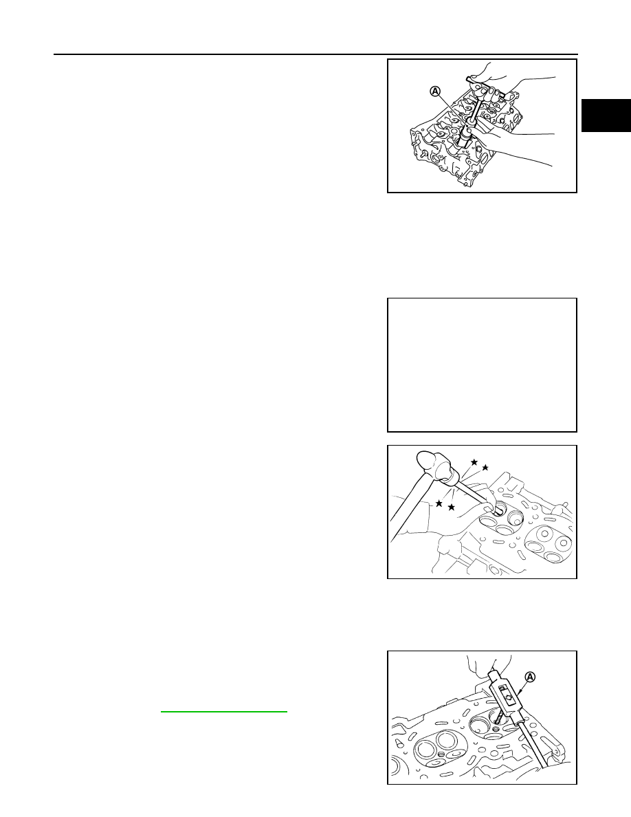
6.
Remove valve oil seal with the valve oil seal puller [SST:
KV10107902] (A).
7.
Remove valve spring seat.
8.
Remove valve seat, if valve seat must be replaced.
• Bore out old seat until it collapses. Boring should not continue beyond the bottom face of the seat
recess in cylinder head. Set the machine depth stop to ensure this.
CAUTION:
Never bore excessively to prevent cylinder head from scratching.
9.
Remove valve guide, if valve guide must be replaced.
a.
To remove valve guide, heat cylinder head to 110 to 130
°
C (230
to 266
°
F) by soaking in heated oil (A).
b.
Drive out valve guide with a press [under a 20 kN (2 ton, 2.2 US
ton, 2.0 lmp ton) pressure] or a hammer and the valve guide drift
(commercial service tool).
WARNING:
Cylinder head contains heat. Wear protective equipment to
avoid getting burned.
ASSEMBLY
1.
When valve guide is removed, install it.
CAUTION:
Replace with oversize [0.2 mm (0.008 in)] valve guide.
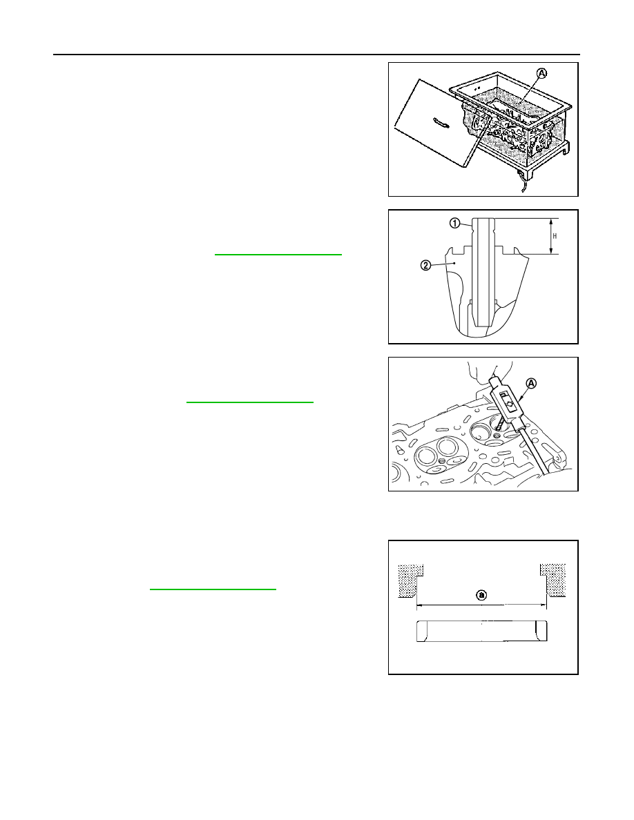
a.
Using the valve guide reamer (commercial service tool) (A),
ream cylinder head valve guide hole.
PBIC3728E
JPBIA0184ZZ
SEM931C
For service parts: Oversized [0.2 mm (0.008 in)]
PBIC3215J
EM-78
< ON-VEHICLE REPAIR >
[HR16DE]
CYLINDER HEAD
b.
Heat cylinder head to 110 to 130
°
C (230 to 266
°
F) by soaking in
heated oil (A).
c.
Using the valve guide drift (commercial service tool), press valve
guide (1) from camshaft side to the dimensions as in the figure.
WARNING:
Cylinder head (2) contains heat. Wear protective equipment
to avoid getting burned.
d.
Using the valve guide reamer (commercial service tool) (A),
apply reamer finish to valve guide.
2.
When valve seat is removed, install it.
CAUTION:
Replace with oversize [0.5 mm (0.020 in)] valve seat.
a.
Ream cylinder head recess diameter (a) for service valve seat.
• Be sure to ream in circles concentric to valve guide center.
This will enable valve to fit correctly.
PBIC3214J
Projection “H”: Refer to
PBIC3217J
PBIC3215J
For service parts: Oversize [0.5 mm (0.020 in)]
Refer to
JPBIA0188ZZ
CYLINDER HEAD
EM-79
< ON-VEHICLE REPAIR >
[HR16DE]
C
D
E
F
G
H
I
J
K
L
M
A
EM
N
P
O
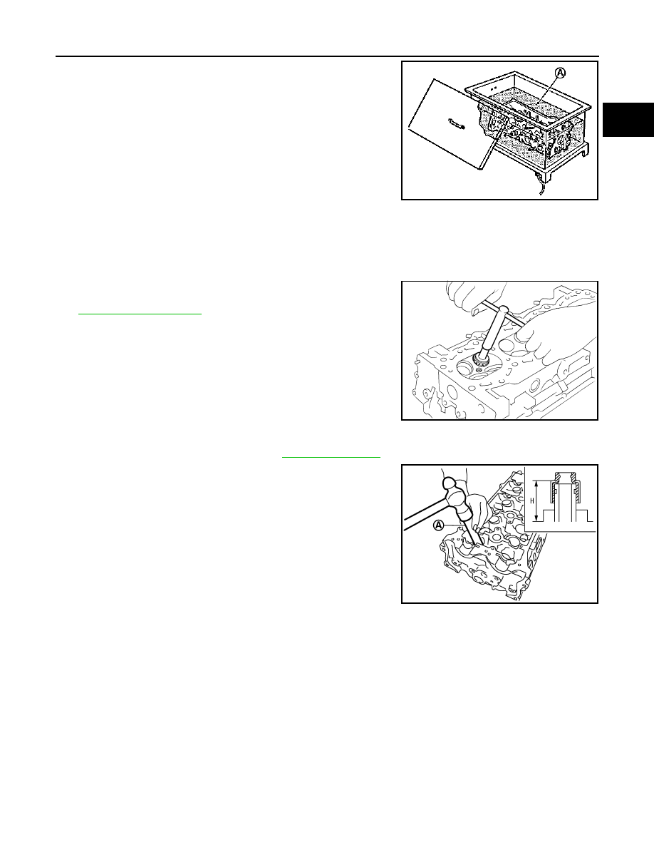
b.
Heat cylinder head to 110 to 130
°
C (230 to 266
°
F) by soaking in
heated oil (A).
c.
Provide valve seats cooled well with dry ice. Force fit valve seat into cylinder head.
WARNING:
Cylinder head contains heat. Wear protective equipment to avoid getting burned.
CAUTION:
Avoid directly touching cold valve seats.
d.
Using the valve seat cutter set (commercial service tool) or valve
seat grinder, finish seat to the specified dimensions. Refer to
.
CAUTION:
When using the valve seat cutter, firmly grip cutter handle
with both hands. Then, press on the contacting surface all
around the circumference to cut in a single drive. Improper
pressure on with cutter or cutting many different times may
result in stage valve seat.
e.
Using compound, grind to adjust valve fitting.
f.
Check again for normal contact. Refer to
3.
Install valve oil seal.
• Install with the valve oil seal drift [SST: KV10115600] (A) to
match dimension in the figure.
4.
Install valve spring seat.
5.
Install valve.
• Install larger diameter to intake side.
6.
Install valve spring.
NOTE:
It can be installed in either direction.
7.
Install valve spring retainer.
8.
Install valve collet.
PBIC3214J
SEM934C
Height “H”
: 13.2 - 13.8 mm (0.520 - 0.543 in)
PBIC3211J
Нет комментариевНе стесняйтесь поделиться с нами вашим ценным мнением.
Текст