Nissan Qashqai (2007-2010). Manual — part 35

EM-88
< DISASSEMBLY AND ASSEMBLY >
[HR16DE]
ENGINE UNIT
ENGINE UNIT
Disassembly
INFOID:0000000000893875
1.
Remove intake manifold. Refer to
2.
Remove exhaust manifold. Refer to
.
3.
Remove oil pan (lower). Refer to
4.
Remove ignition coil, spark plug and rocker cover. Refer to
5.
Remove fuel injector and fuel tube. Refer to
6.
Remove timing chain. Refer to
.
7.
Remove camshaft. Refer to
8.
Remove cylinder head. Refer to
Assembly
INFOID:0000000000893876
Assembly is the reverse order of disassembly.
OIL PAN (UPPER)
EM-89
< DISASSEMBLY AND ASSEMBLY >
[HR16DE]
C
D
E
F
G
H
I
J
K
L
M
A
EM
N
P
O
OIL PAN (UPPER)
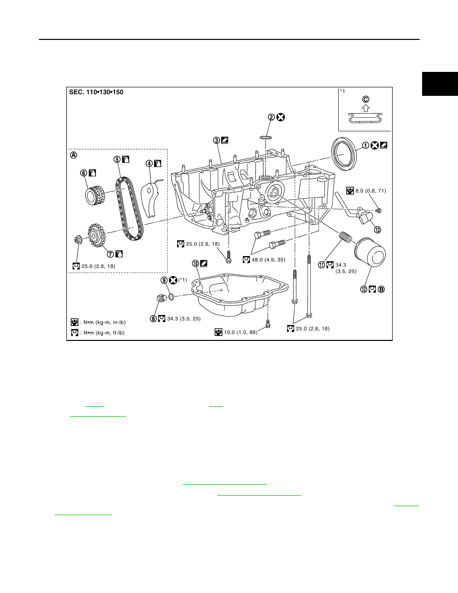
Exploded View
INFOID:0000000000894028
Removal and Installation
INFOID:0000000000894027
NOTE:
The oil strainer and oil pump are included in the oil pan (upper). Individual disassembly is prohibited.
REMOVAL
1.
Remove the oil pan (lower). Refer to
2.
Remove front cover and timing chain. Refer to
.
3.
Remove oil pump sprocket and crankshaft sprocket together with oil pump drive chain. Refer to
4.
Remove oil pan (upper) with the following procedure.
1.
Rear oil seal
2.
O-ring
3.
Oil pan (upper)
4.
Chain tensioner
5.
Oil pump drive chain
6.
Crankshaft sprocket
7.
Oil pump sprocket
8.
Oil pan drain plug
9.
Washer
10.
Oil pan (lower)
11.
Oil filter stud bolt
12.
Oil filter
13.
Oil level sensor
A.
B.
Refer to
C.
Oil pan side
for symbols in the figure.
JPBIA0553GB
EM-90
< DISASSEMBLY AND ASSEMBLY >
[HR16DE]
OIL PAN (UPPER)
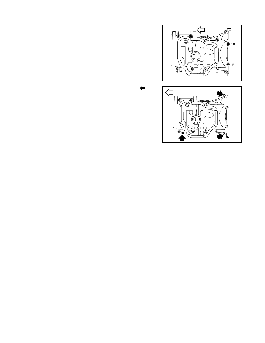
a.
Loosen oil pan (upper) mounting bolts in the reverse of the order
shown in the figure.
b.
Insert a flat-bladed offset screwdriver into the arrow (
) in the
figure and open up a crack between the oil pan (upper) cylinder
block.
c.
Insert the seal cutter [SST: KV10111100] between remove the oil
pan (upper) and cylinder block. Slide seal cutter by tapping on
the side of tool with a hammer.
CAUTION:
• Be careful not to damage the mating surface.
• A more adhesive liquid gasket is applied compared to pre-
vious types when shipped, so it should not be forced off using a screwdriver, etc. outside the
indicated location.
• Never remove oil pump and oil strainer from oil pan (upper).
5.
Remove oil level sensor, if necessary.
6.
Remove rear oil seal from crankshaft.
INSTALLATION
1.
Install the oil pan (upper) in the following procedure.
a.
Use scraper to remove old liquid gasket from mating surfaces.
• Also remove the old liquid gasket from mating surface of cylinder block.
• Remove old liquid gasket from the bolt holes and threads.
CAUTION:
Never scratch or damage the mating surfaces when cleaning off old liquid gasket.
b.
Install O-ring to the cylinder block.
: Engine front
MBIB1374E
: Engine front
MBIB1375E
OIL PAN (UPPER)
EM-91
< DISASSEMBLY AND ASSEMBLY >
[HR16DE]
C
D
E
F
G
H
I
J
K
L
M
A
EM
N
P
O
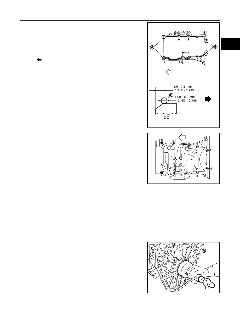
c.
Apply a continuous bead of liquid gasket (C) with the tube
presser (commercial service tool) to areas shown in the figure.
Use Genuine Liquid Gasket or equivalent.
CAUTION:
Attaching should be done within 5 minutes after coating.
d.
Tighten bolts in the numerical order shown in the figure.
CAUTION:
Install avoiding misalignment of both oil pan gasket and O-
ring.
• The bolts are different according to the installation position.
Refer to the numbers shown in the figure.
2.
Install rear oil seal.
CAUTION:
• The installation of rear oil seal should be completed within 5 minutes after installing oil pan
(upper).
• Never touch oil seal lip.
a.
Wipe off any liquid gasket protruding to the rear oil seal mounting part of oil pan (upper) and cylinder block
using a spatula.
b.
Apply the liquid gasket lightly to entire outside area of new rear oil seal.
Use Genuine Liquid Gasket or equivalent.
c.
Press-fit the rear oil seal using a drift with outer diameter 113
mm (4.45 in) and inner diameter 90 mm (3.54 in) (commercial
service tool) (A).
A
: 2 mm (0.08 in) protruded to outside
B
: 2 mm (0.08 in) protruded to rear oil seal mounting side
: Engine front
: Oil pan out side
PBIC4344E
: Engine front
M8
×
179 mm (7.05 in)
: No. 9, 10
M8
×
25 mm (0.98 in)
: No. 4, 7, 8
M8
×
90 mm (3.54 in)
: No. 1, 2, 3, 5, 6
MBIB1374E
PBIC3660E
Нет комментариевНе стесняйтесь поделиться с нами вашим ценным мнением.
Текст