Nissan Qashqai (2007-2010). Manual — part 550
TRANSAXLE ASSEMBLY
TM-135
< DISASSEMBLY AND ASSEMBLY >
[6MT: RS6F52A]
C
E
F
G
H
I
J
K
L
M
A
B
TM
N
O
P
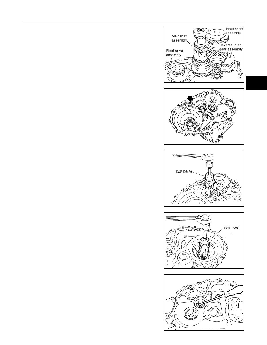
30. Remove gear components from clutch housing in the following
procedure.
a.
Remove a set of input shaft assembly, mainshaft assembly, and
reverse idler gear assembly by tapping the tip of input shaft from
the back of the clutch housing with a plastic hammer.
CAUTION:
Always withdraw mainshaft straight out. Failure to do so
can damage resin oil channel on clutch housing side.
b.
Remove final drive assembly.
31. Remove magnet from clutch housing.
32. Remove mainshaft bearing retainer and then mainshaft front
bearing from clutch housing using the puller.
CAUTION:
Never damage clutch housing, mainshaft front bearing, and
oil channel.
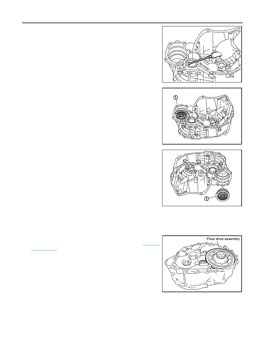
33. Remove oil channel from clutch housing.
34. Remove differential side bearing outer race (clutch housing
side) from clutch housing using the puller.
CAUTION:
Never damage clutch housing and differential side bearing
outer race.
35. Remove input shaft oil seal from clutch housing.
CAUTION:
Never damage clutch housing.
SCIA0964E
PCIB1859E
SCIA1077J
SCIA1069J
SCIA0398E
TM-136
< DISASSEMBLY AND ASSEMBLY >
[6MT: RS6F52A]
TRANSAXLE ASSEMBLY
36. Remove differential side oil seal from clutch housing.
CAUTION:
Never damage clutch housing.
37. Remove snap ring (1) from clutch housing.
CAUTION:
Never damage clutch housing.
38. With output gear assembly (1) held by hand, turn clutch housing
upside down as shown in the figure.
CAUTION:
• When turning clutch housing upside down, hold output
gear assembly by hand so that it will not become
detached.
• Never damage clutch housing.
NOTE:
Output gear assembly spontaneously falls when changing the
clutch housing direction as shown in the figure.
39. With output gear assembly held by hand, slowly remove output
gear assembly from clutch housing. If output gear assembly can
not be removed, tap it with a plastic hammer from the transaxle case contact surface side of clutch hous-
ing for removal.
Assembly
INFOID:0000000001034953
1.
Install final drive assembly into clutch housing.
2.
Select differential side bearing adjusting shim. Refer to
CAUTION:
Never select differential side bearing adjusting shim with
output gear assembly installed on clutch housing.
3.
Remove final drive assembly.
JPDIC0076ZZ
JPDIC0044ZZ
JPDIC0075ZZ
SCIA0888E
TRANSAXLE ASSEMBLY
TM-137
< DISASSEMBLY AND ASSEMBLY >
[6MT: RS6F52A]
C
E
F
G
H
I
J
K
L
M
A
B
TM
N
O
P
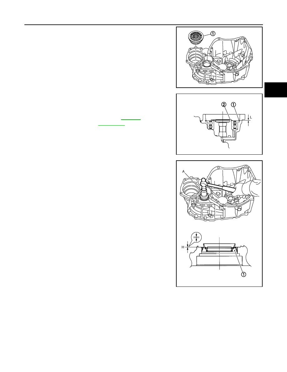
4.
Turn clutch housing upside down as shown in the figure. And
then install output gear assembly (1) into clutch housing.
CAUTION:
• Gently install it, aligning the clutch housing hole with the
center of output gear assembly.
• Install output gear assembly, straightening it with a mag-
net.
• Never damage clutch housing and output gear assembly.
5.
Install snap ring (1) onto clutch housing and make sure that end
play (gap between snap ring and groove) of output gear assem-
bly (2) satisfies the standard value.
CAUTION:
• Only one snap ring can be selected.
• Never reuse snap ring.
• Never damage clutch housing.
6.
Install differential side oil seal (1) to clutch housing using the drift
(A) [SST: ST33400001].
CAUTION:
• Never reuse differential side oil seal.
• When installing, never incline differential side oil seal.
• Never damage clutch housing.
JPDIC0074ZZ
End play standard val-
ue “L”
: Refer to
JPDIC0043ZZ
Dimension “H”
: -0.5 - 0.5 mm (-0.020 - 0.020 in)
JPDIC0077ZZ
TM-138
< DISASSEMBLY AND ASSEMBLY >
[6MT: RS6F52A]
TRANSAXLE ASSEMBLY
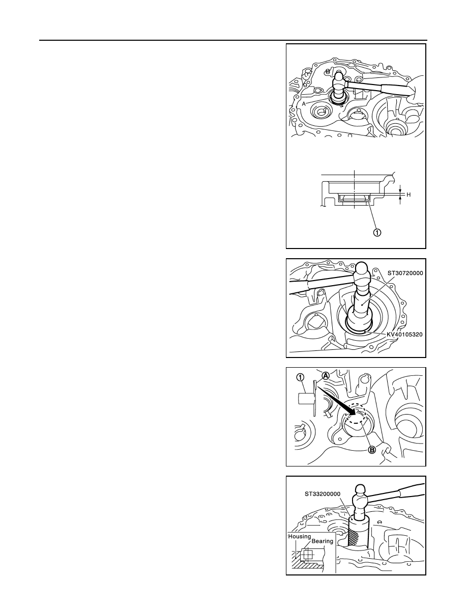
7.
Install input shaft oil seal (1) to clutch housing using the drift (A)
[SST: ST35321000].
CAUTION:
• Never reuse input shaft oil seal.
• When installing, never incline input shaft oil seal.
• Never damage clutch housing.
8.
Install differential side bearing outer race (clutch housing side) to
clutch housing using the drifts.
CAUTION:
Replace differential side bearing and differential side bear-
ing outer race as a set.
9.
Install oil channel (1) on mainshaft side.
CAUTION:
When installing oil channel, fit the rib (A) of oil channel into
the processed area of the spot facing (B).
10. Install mainshaft front bearing to clutch housing using the drift.
CAUTION:
Be careful with the orientation of mainshaft front bearing.
Dimension “H”
: 1.1 - 2.1 mm (0.043 - 0.083 in)
PCIB1814E
SCIA0987E
PCIB1921E
SCIA0401E
Нет комментариевНе стесняйтесь поделиться с нами вашим ценным мнением.
Текст