Nissan Qashqai (2007-2010). Manual — part 551
TRANSAXLE ASSEMBLY
TM-139
< DISASSEMBLY AND ASSEMBLY >
[6MT: RS6F52A]
C
E
F
G
H
I
J
K
L
M
A
B
TM
N
O
P
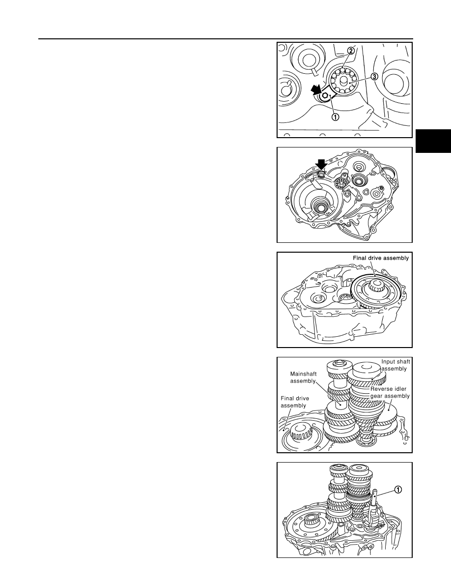
11. Install mainshaft bearing retainer (1) to clutch housing and
tighten mounting bolt to the specified torque.
CAUTION:
Install with punched surface facing up.
12. Install magnet to clutch housing.
13. Install final drive assembly into clutch housing.
CAUTION:
Engage reduction gear teeth in output gear teeth.
14. Install input shaft assembly, mainshaft assembly, and reverse
idler gear assembly into clutch housing.
CAUTION:
• Wrap a tape, etc. to the spline of input shaft so as not to
damage the input shaft oil seal.
• Be careful with the orientation of reverse idler shaft.
15. Install striking rod assembly (1) into clutch housing.
2
: Mainshaft front bearing
3
: Oil channel
PCIB1938E
PCIB1859E
SCIA0888E
SCIA0964E
PCIB1857E
TM-140
< DISASSEMBLY AND ASSEMBLY >
[6MT: RS6F52A]
TRANSAXLE ASSEMBLY
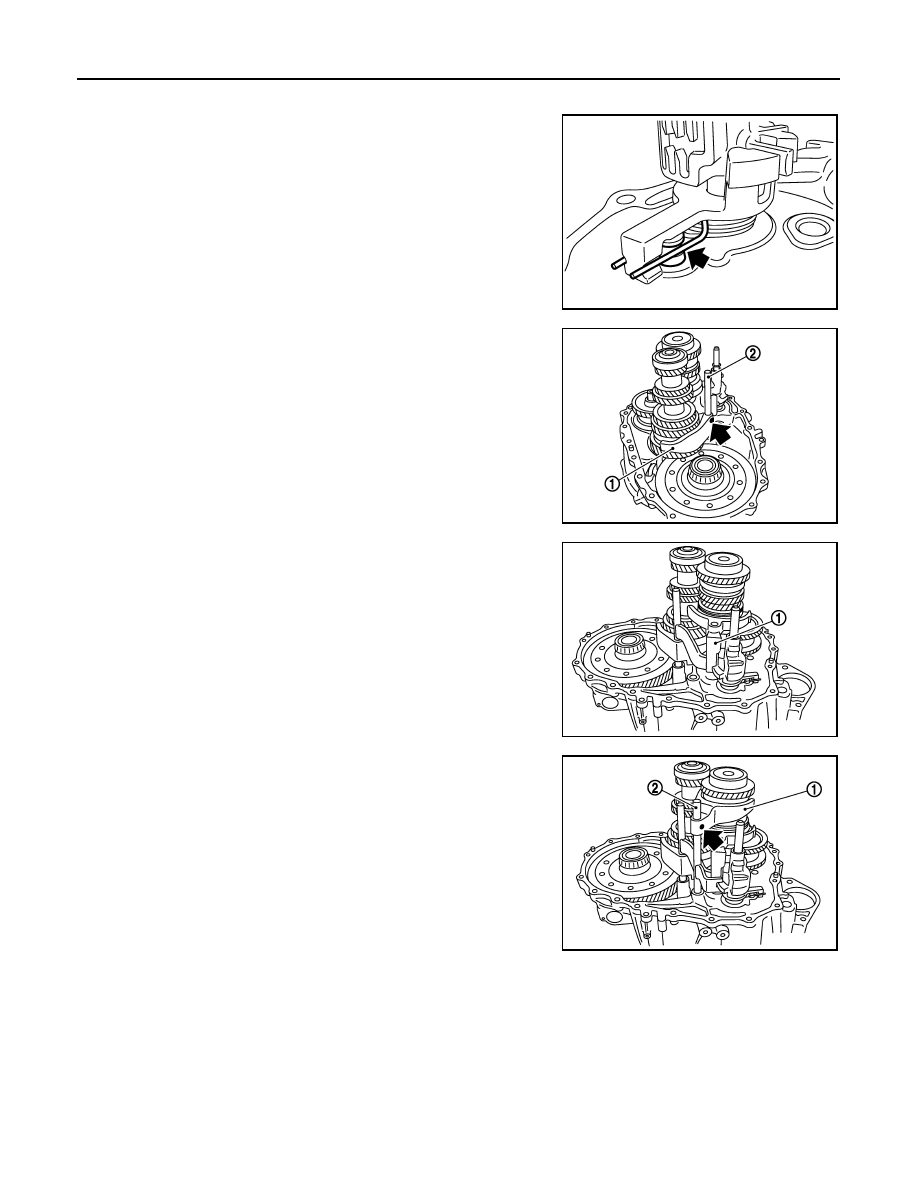
CAUTION:
Check that return spring is securely seated in the groove on
return pin.
16. Install 1st-2nd shift fork (1) and 1st-2nd fork rod (2) and then
install retaining pin to 1st-2nd shift fork.
CAUTION:
• Never reuse retaining pin.
• Be careful with the orientation of 1st-2nd shift fork and
1st-2nd fork rod.
• Assemble retaining pin from the direction shown by the
arrow in the figure until it becomes flush with the end sur-
face of 1st-2nd shift fork.
17. Install 3rd-4th shift fork (1) to 3rd-4th coupling sleeve.
CAUTION:
Be careful with the orientation of 3rd-4th shift fork.
18. Install 5th-6th shift fork (1) and 5th-6th fork rod (2) and then
install retaining pin to 5th-6th shift fork.
CAUTION:
• Never reuse retaining pin.
• Be careful with the orientation of 5th-6th shift fork and
5th-6th fork rod.
• Assemble retaining pin from the direction shown by the
arrow in the figure until it becomes flush with the end sur-
face of 5th-6th shift fork.
PCIB1866E
PCIB1856E
PCIB1855E
PCIB1852E
TRANSAXLE ASSEMBLY
TM-141
< DISASSEMBLY AND ASSEMBLY >
[6MT: RS6F52A]
C
E
F
G
H
I
J
K
L
M
A
B
TM
N
O
P
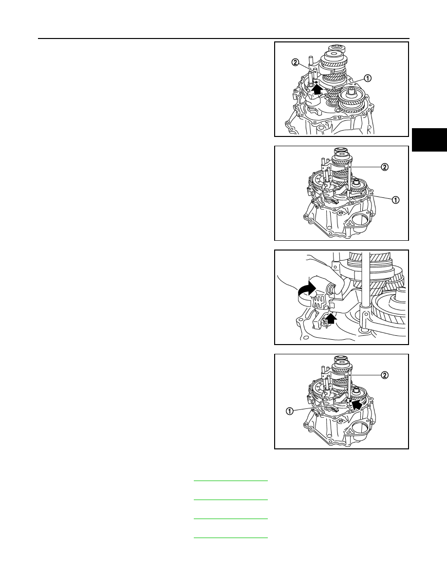
19. Install 3rd-4th fork rod (2) and then install retaining pin to 3rd-4th
shift fork (1).
CAUTION:
• Never reuse retaining pin.
• Be careful with the orientation of 3rd-4th fork rod.
• Assemble retaining pin from the direction shown by the
arrow in the figure until it becomes flush with the end sur-
face of 3rd-4th shift fork.
20. Install reverse shift fork (1) and reverse fork rod (2).
CAUTION:
Be careful with the orientation of reverse shift fork and
reverse fork rod.
21. Rotate striking lever of striking rod assembly as shown in the fig-
ure. Then rotate reverse fork rod to a position where bracket of
reverse fork rod does not interfere with striking lever of striking
rod assembly.
22. Install retaining pin to reverse shift fork (1).
CAUTION:
• Never reuse retaining pin.
• Assemble retaining pin from the direction shown by the
arrow in the figure until it becomes flush with the end sur-
face of reverse shift fork.
23. Install selected differential side bearing adjusting shim and differential side bearing outer race (transaxle
case side).
• For selection of adjusting shim, refer to
.
24. Install selected reverse idler gear adjusting shim onto reverse idler gear assembly.
• For selection of adjusting shim, refer to
.
25. Install selected input shaft rear bearing adjusting shim onto input shaft.
• For selection of adjusting shim, refer to
.
26. Install selected striking rod adjusting shim and striking rod shim onto striking rod assembly.
• For selection of adjusting shim, refer to
.
PCIB1853E
PCIB1875E
PCIB1851E
2
: Reverse fork rod
PCIB1850E
TM-142
< DISASSEMBLY AND ASSEMBLY >
[6MT: RS6F52A]
TRANSAXLE ASSEMBLY
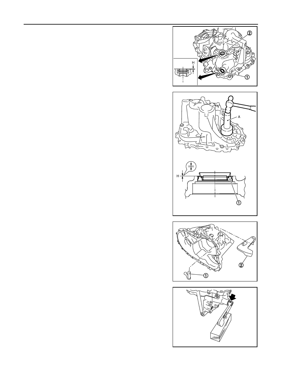
27. Install shifter lever oil seal (1) and striking rod oil seal (2) to tran-
saxle case using the drift [Commercial service tool].
CAUTION:
• Never reuse shifter lever oil seal and striking rod oil seal.
• When installing, never incline shifter lever oil seal and
striking rod oil seal.
• Never damage transaxle case.
28. Install differential side oil seal (1) to transaxle case using the drift
(A) [SST: ST30720000].
CAUTION:
• Never reuse differential side oil seal.
• When installing, never incline differential side oil seal.
• Never damage transaxle case.
29. Install shifter lever B (1) and shifter lever A (2) to transaxle case.
CAUTION:
Be careful with the orientation of shifter lever B and shifter
lever A.
30. Install retaining pin to shifter lever A.
CAUTION:
• Never reuse retaining pin.
• Assemble retaining pin from the direction shown by the
arrow in the figure until it becomes flush with the end sur-
face of shifter lever A.
Dimension “H”
: 0 - 1.0 mm (0 - 0.039 in)
PCIB1818E
Dimension “H”
: -0.5 - 0.5 mm (-0.020 - 0.020 in)
PCIB1878E
PCIB1843E
PCIB1844E
Нет комментариевНе стесняйтесь поделиться с нами вашим ценным мнением.
Текст