Nissan Qashqai (2007-2010). Manual — part 549
TRANSAXLE ASSEMBLY
TM-131
< DISASSEMBLY AND ASSEMBLY >
[6MT: RS6F52A]
C
E
F
G
H
I
J
K
L
M
A
B
TM
N
O
P
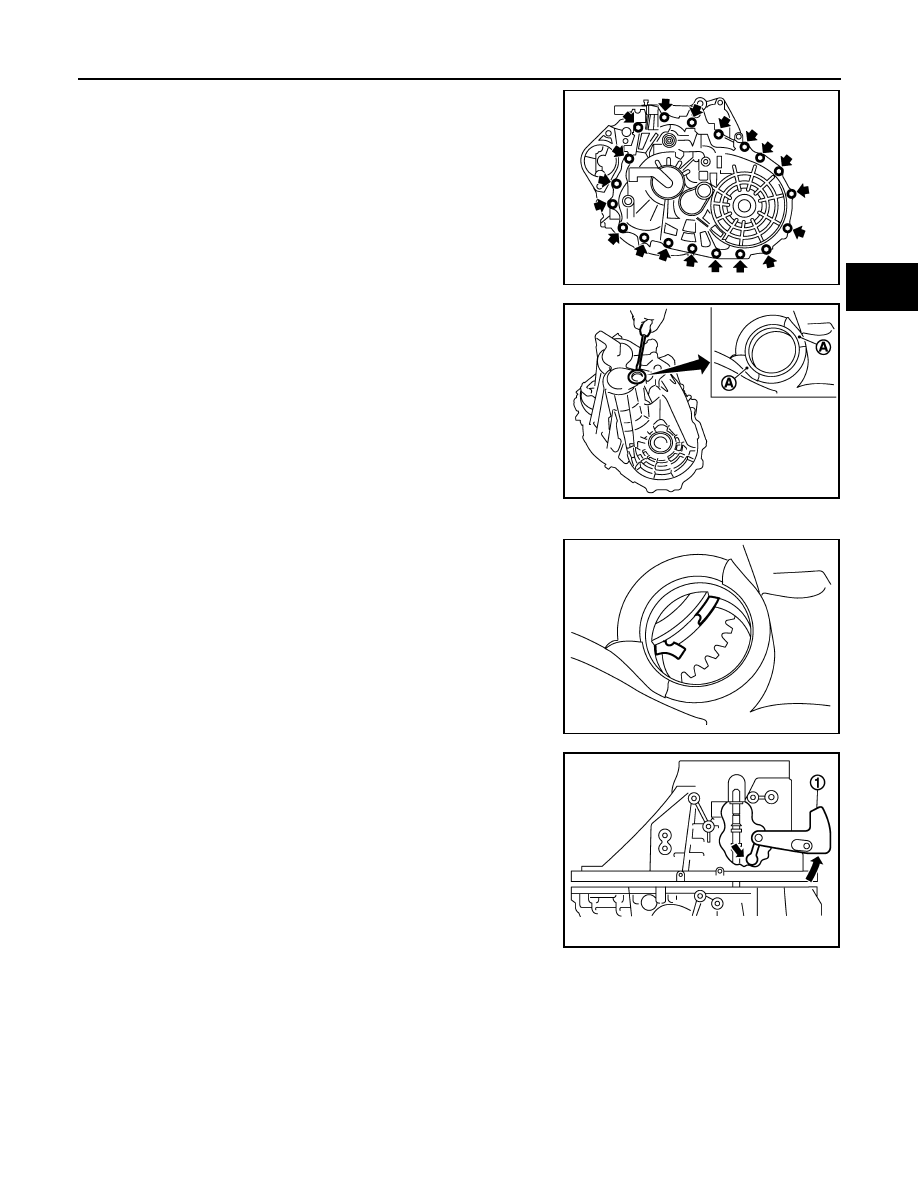
9.
Remove transaxle case mounting bolts.
10. Remove bore plug from transaxle case.
CAUTION:
• Never damage transaxle case.
• Access bore plug from cutout (A) of transaxle case when
removing.
11. Remove transaxle case following the procedures below.
a.
Expand snap ring at mainshaft rear bearing accessing from the
bore plug hole. Then pull up transaxle case from clutch housing
until snap ring comes off.
b.
With shifter lever A (1) held in the position shown in the figure,
remove transaxle case from clutch housing.
CAUTION:
Never drop each adjusting shim.
NOTE:
Make sure to hold shifter lever A in the position shown in the fig-
ure. Otherwise transaxle case cannot be removed from clutch
housing.
PCIB1838E
PCIB1839E
PCIB1840E
PCIB1808E
TM-132
< DISASSEMBLY AND ASSEMBLY >
[6MT: RS6F52A]
TRANSAXLE ASSEMBLY
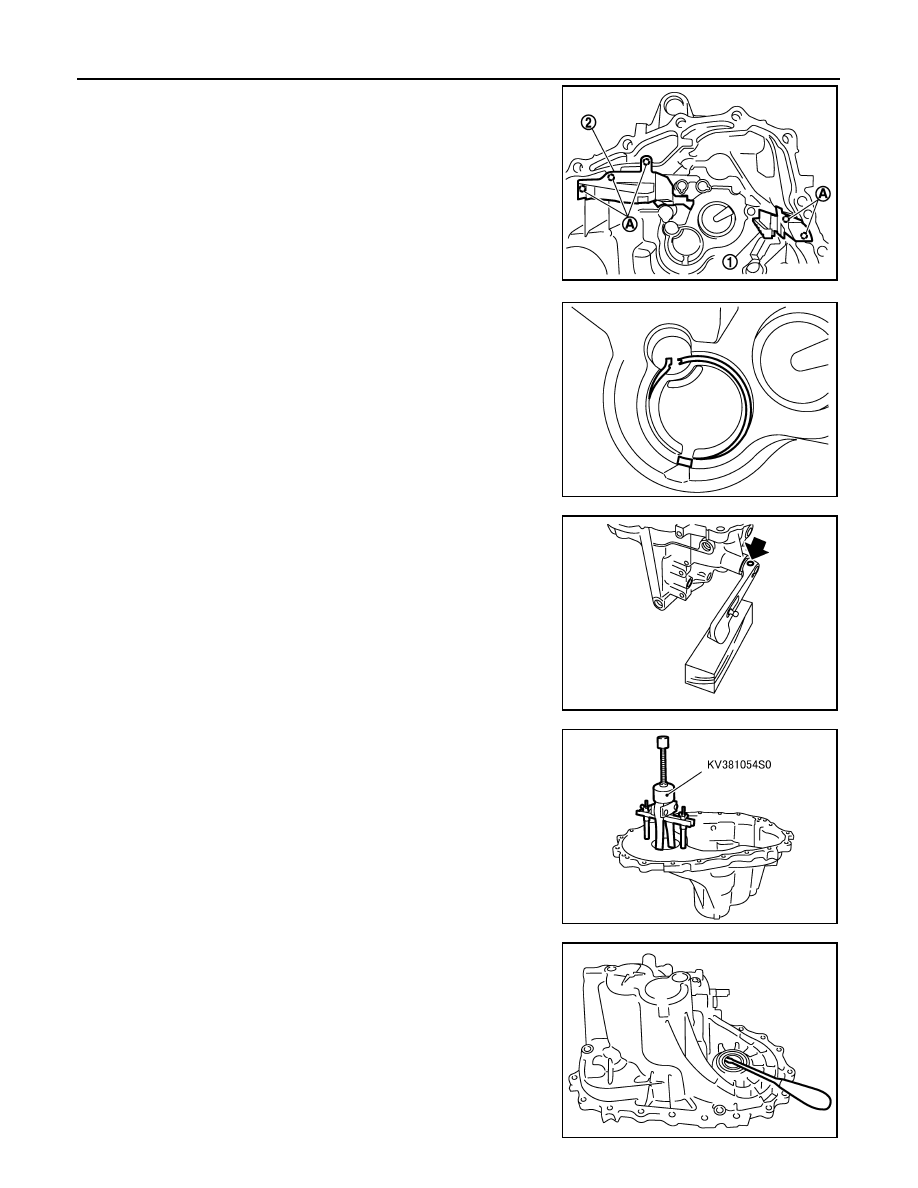
12. Remove oil gutter A (1) and oil gutter B (2) from transaxle case.
13. Remove snap ring from transaxle case.
14. Remove retaining pin using a pin punch and then remove shifter
lever A and shifter lever B from transaxle case.
15. Remove differential side bearing outer race (transaxle case
side) from transaxle case using the puller and then remove dif-
ferential side bearing adjusting shim from transaxle case.
CAUTION:
Never damage transaxle case and differential side bearing
outer race.
16. Remove differential side oil seal from transaxle case.
CAUTION:
Never damage transaxle case.
A
: Tab of oil gutter
PCIB1841E
PCIB1842E
PCIB1844E
SCIA0897E
SCIA0397E
TRANSAXLE ASSEMBLY
TM-133
< DISASSEMBLY AND ASSEMBLY >
[6MT: RS6F52A]
C
E
F
G
H
I
J
K
L
M
A
B
TM
N
O
P
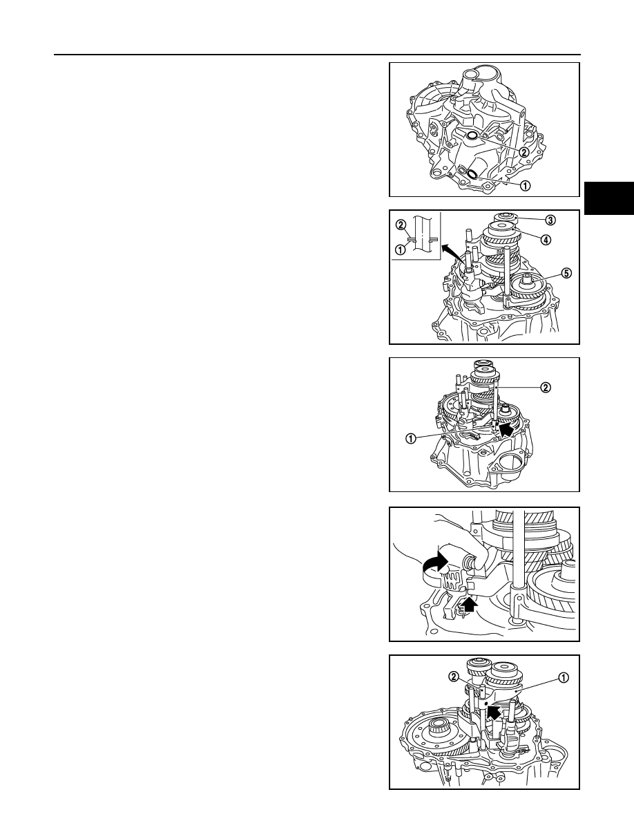
17. Remove shifter lever oil seal (1) and striking rod oil seal (2) from
transaxle case.
CAUTION:
Never damage transaxle case.
18. Remove striking rod shim (1), striking rod adjusting shim (2),
mainshaft rear bearing adjusting shim (3), input shaft rear bear-
ing adjusting shim (4), and reverse idler gear adjusting shim (5).
19. Remove retaining pin of reverse shift fork (1) using a pin punch.
20. Rotate striking lever of striking rod assembly as shown in the fig-
ure. Then rotate reverse fork rod to a position where bracket of
reverse fork rod does not interfere with striking lever of striking
rod assembly.
21. Pull out reverse shift fork and reverse fork rod.
22. Remove retaining pin of 5th-6th shift fork (1) using a pin punch.
PCIB1846E
PCIB1858E
2
: Reverse fork rod
PCIB1850E
PCIB1851E
2
: 5th-6th fork rod
PCIB1852E
TM-134
< DISASSEMBLY AND ASSEMBLY >
[6MT: RS6F52A]
TRANSAXLE ASSEMBLY
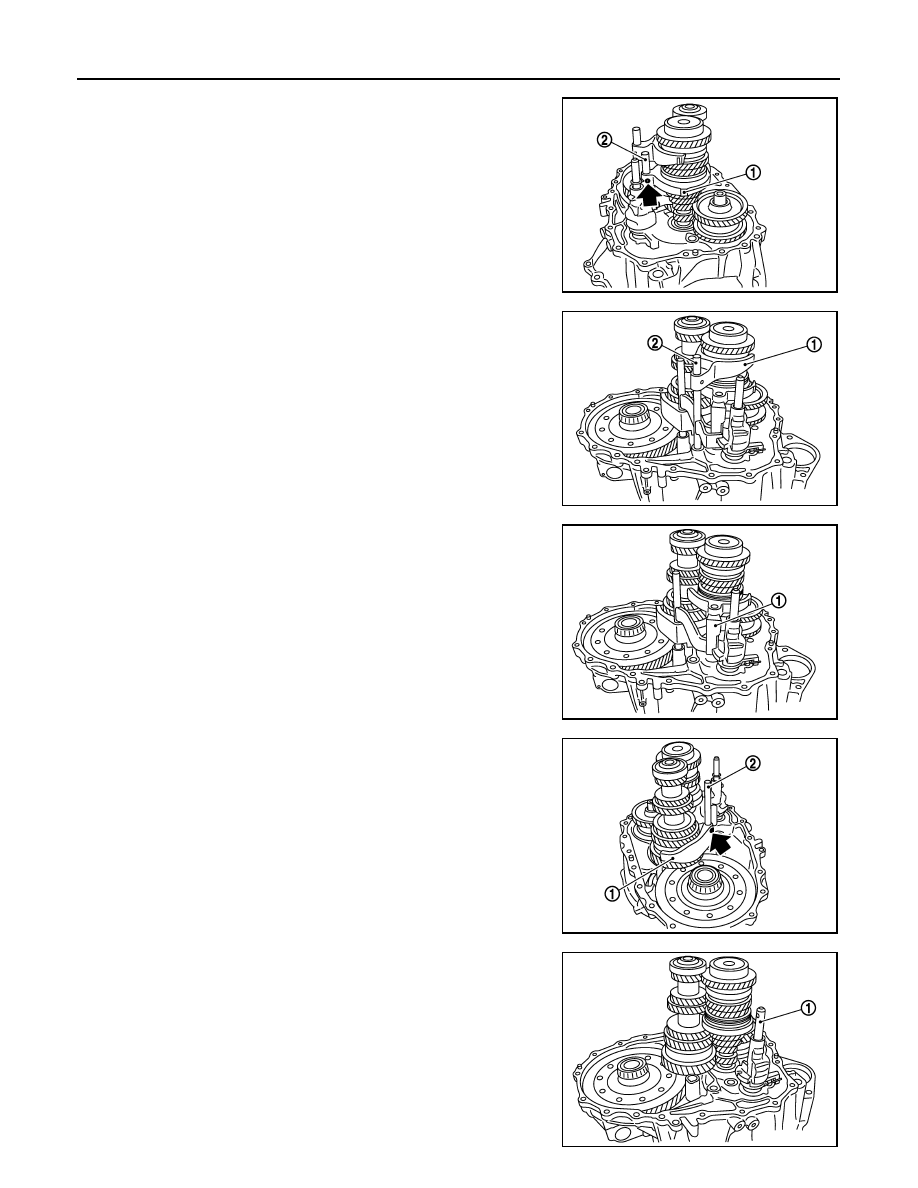
23. Remove retaining pin of 3rd-4th shift fork (1) using a pin punch.
24. Pull out 3rd-4th fork rod (2).
25. Pull out 5th-6th shift fork (1) and 5th-6th fork rod (2).
26. Pull out 3rd-4th shift fork (1).
27. Remove retaining pin of 1st-2nd shift fork (1) using a pin punch.
28. Pull out 1st-2nd shift fork and 1st-2nd fork rod (2).
29. Remove striking rod assembly (1).
PCIB1853E
PCIB1854E
PCIB1855E
PCIB1856E
PCIB1857E
Нет комментариевНе стесняйтесь поделиться с нами вашим ценным мнением.
Текст