Nissan Qashqai (2007-2010). Manual — part 948

HAC-152
< COMPONENT DIAGNOSIS >
[MANUAL AIR CONDITIONER]
INTAKE DOOR MOTOR
6.
CHECK FUSE
Check 10A fuse [No.4, located in the fuse block (J/B)]. Refer to
PG-110, "Fuse, Connector and Terminal
Is the inspection result normal?
YES
>> Repair harness or connector.
NO
>> Replace fuse.
BLOWER MOTOR
HAC-153
< COMPONENT DIAGNOSIS >
[MANUAL AIR CONDITIONER]
C
D
E
F
G
H
J
K
L
M
A
B
HAC
N
O
P
BLOWER MOTOR
Description
INFOID:0000000001069968
COMPONENT DESCRIPTION
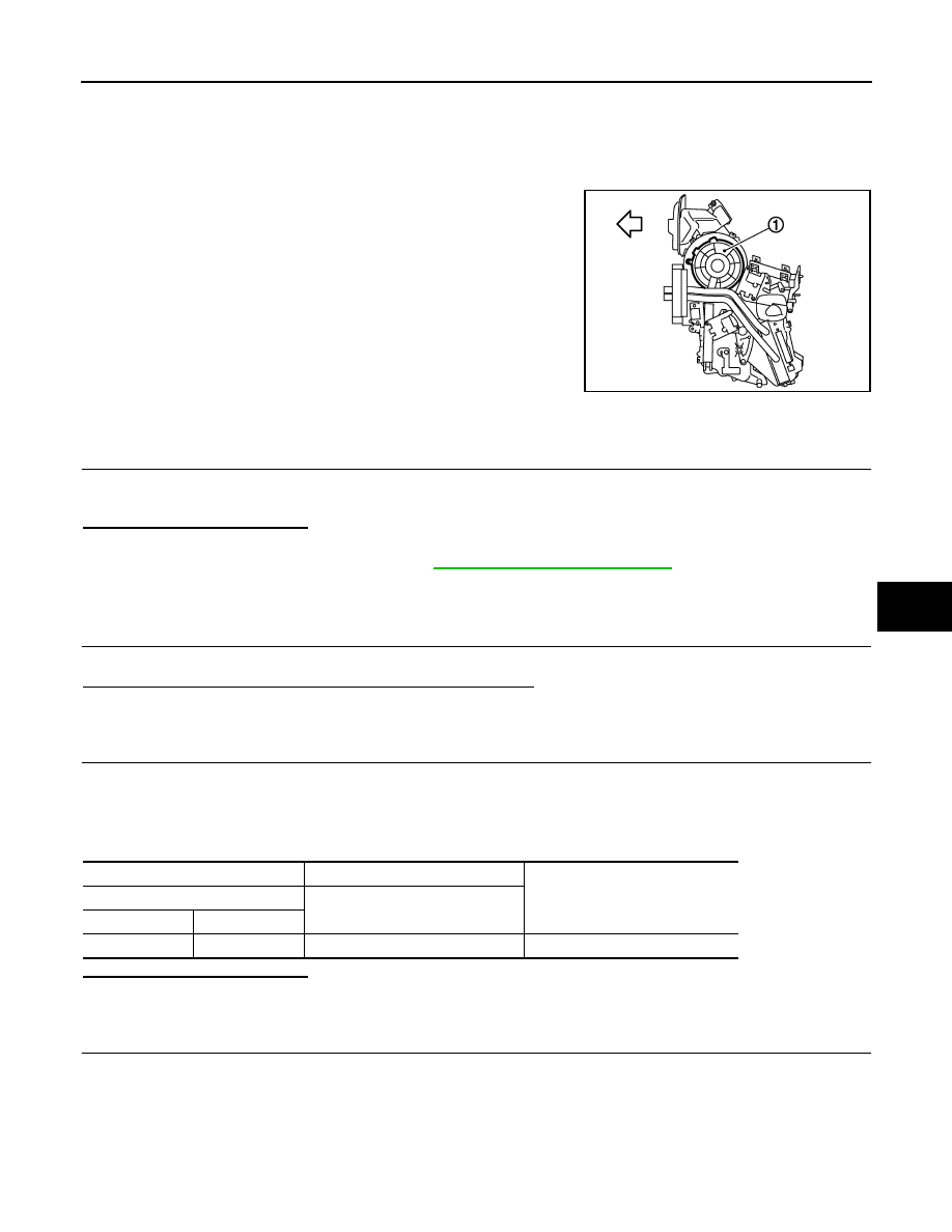
The blower motor (1) utilizes a brush motor with a sirocco fan type.
Component Function Check
INFOID:0000000001069969
1.
CONFIRM SYMPTOM BY PERFORMING THE FOLLOWING OPERATIONAL CHECK
1.
Turn fan control dial clockwise. Blower should operate on low speed.
2.
Turn fan control dial clockwise, and continue checking blower speed until all speeds checked.
Is the inspection result normal?
YES
>> END.
NO
>> Go to diagnosis procedure. Refer to
HAC-153, "Diagnosis Procedure"
Diagnosis Procedure
INFOID:0000000001069970
1.
CHECK BLOWER MOTOR OPERATING
Check blower motor operating.
Is blower motor operation under starting blower speed control?
YES
>> END.
NO
>> Blower motor dose not operate: GO TO 2.
2.
CHECK POWER SUPPLY FOR BLOWER MOTOR
1.
Turn ignition switch OFF.
2.
Disconnect blower motor connector.
3.
Turn ignition switch ON.
4.
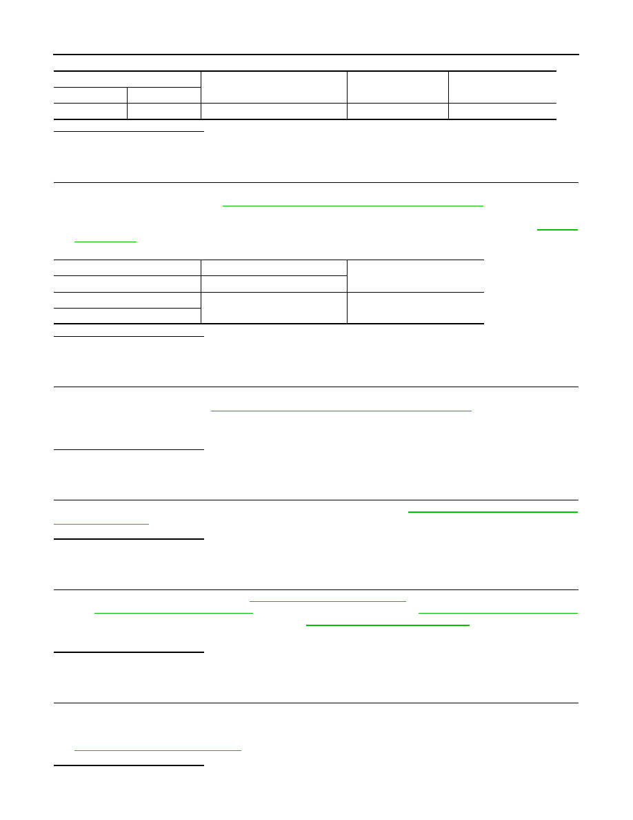
Check voltage between blower motor harness connector M312 terminal 1 and ground.
Is the inspection result normal?
OK
>> GO TO 3.
NG
>> GO TO 4.
3.
CHECK BLOWER MOTOR GROUND CIRCUIT
1.
Turn ignition switch OFF.
2.
Turn fan control dial clockwise to 4th.
3.
Check continuity between blower motor harness connector M312 terminal 2 and ground.
:
Vehicle front
JPIIA0028ZZ
(+)
(
−
)
Voltage
Blower motor
—
Connector
Terminal
M312
1
Ground
Battery voltage
HAC-154
< COMPONENT DIAGNOSIS >
[MANUAL AIR CONDITIONER]
BLOWER MOTOR
Is the inspection result normal?
YES
>> Replace blower motor.
NO
>> GO TO 10.
4.
CHECK POWER VOLTAGE OF BLOWER RELAY
1.
Turn ignition switch OFF.
2.
Remove blower relay. Refer to
PG-110, "Fuse, Connector and Terminal Arrangement"
.
3.
Turn ignition switch ON.
4.
Check the voltage between blower relay fuse block terminals 1, 3 and body ground. Refer to
for relay terminal assignment.
Is the inspection result normal?
YES
>> GO TO 5.
NO
>> GO TO 7.
5.
CHECK BLOWER RELAY
1.
Turn ignition switch OFF.
2.
Install blower relay. Refer to
PG-110, "Fuse, Connector and Terminal Arrangement"
3.
Turn ignition switch ON.
4.
Check operation sound of the blower relay after switching ignition switch ON.
Is the inspection result normal?
YES
>> GO TO 6.
NO
>> Replace blower relay.
6.
CHECK FUSE
Check 15A fuses [No. 15 and 16, located in the fuse block (J/B)]. Refer to
PG-110, "Fuse, Connector and Ter-
.
Is the inspection result normal?
YES
>> Repair harness or connector.
NG
>> Replace fuse.
7.
CHECK IGNITION SWITCH CIRCUIT
Check ignition switch circuit. Refer to
LOCK),
DLK-355, "Diagnosis Procedure"
(WITH I-KEY & SUPER LOCK),
DLK-597, "Diagnosis Procedure"
(WITHOUT I-KEY, WITHOUT SUPER LOCK) or
DLK-757, "Diagnosis Procedure"
SUPER LOCK).
Is the inspection result normal?
YES
>> Repair harness or connector.
NG
>> Replace malfunctioning parts.
8.
CHECK CIRCUIT CONTINUITY BETWEEN BLOWER FAN RESISTOR.
1.
Turn ignition switch OFF.
2.
Disconnect blower fan resistor connector.
3.
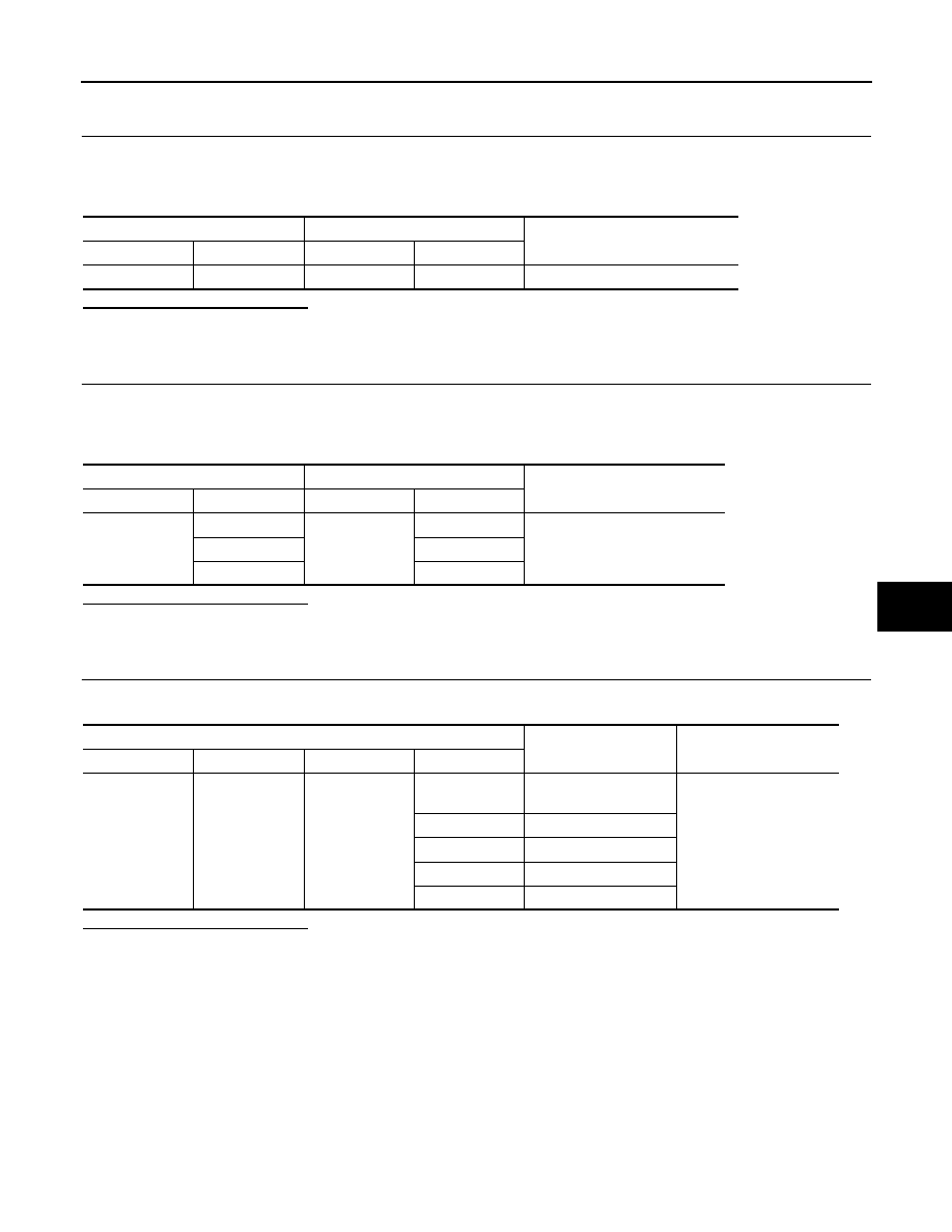
Check continuity between blower fan resistor harness connector M305 terminal 1 and 2, 3, 4. Refer to
HAC-155, "Component Inspection"
Is the inspection result normal?
YES
>> GO TO 9.
Blower motor
—
Condition
Continuity
Connector
Terminal
M312
2
Ground
Fan control dial: 4th
Continuity should exist
(+)
(
−
)
Voltage
Blower relay
—
1
Ground
Battery voltage
3
BLOWER MOTOR
HAC-155
< COMPONENT DIAGNOSIS >
[MANUAL AIR CONDITIONER]
C
D
E
F
G
H
J
K
L
M
A
B
HAC
N
O
P
NO
>> Replace blower fan resistor.
9.
CHECK CIRCUIT CONTINUITY BETWEEN BLOWER MOTOR AND BLOWER FAN RESISTOR
1.
Disconnect blower motor connector.
2.
Check continuity between blower motor harness connector M312 terminal 2 and blower fan resistor M305
terminal 1.
Is the inspection result normal?
OK
>> GO TO 10.
NG
>> Repair harness or connector.
10.
CHECK CIRCUIT CINTINUITY BETWEEN BLOWER MOTOR RESISTOR AND FAN SWITCH
1.
Disconnect fan switch connector.
2.
Check continuity between blower motor resistor harness connector M305 terminal 2, 3, 4 and fan switch
M88 terminal 2, 3, 4.
Is the inspection result normal?
OK
>> GO TO 11.
NG
>> Repair harness or connector.
11.
CHECK FAN SWITCH
Check continuity between fan switch harness connector M88 terminal 5 and 1, 2, 3, 4, 6.
Is the inspection result normal?
YES
>> Repair fan switch ground harness or connector.
NO
>> Replace fan switch.
Component Inspection
INFOID:0000000001069971
BLOWER MOTOR
Blower motor
Blower fan resistor
Continuity
Connector
Terminal
Connector
Terminal
M312
2
M305
1
Continuity should exist
Blower fan resistor
Fan SW
Continuity
Connector
Terminal
Connector
Terminal
M305
2
M88
2
Continuity should exist
3
3
4
4
FAN SW
Condition
Continuity
Connector
Terminal
Connector
Terminal
M88
5
M88
6
Fan control dial: except
OFF
Continuity should exist
4
Fan control dial: 1st
3
Fan control dial: 2nd
2
Fan control dial: 3rd
1
Fan control dial: 4th
Нет комментариевНе стесняйтесь поделиться с нами вашим ценным мнением.
Текст