Nissan Qashqai (2007-2010). Manual — part 711
BRC-42
< COMPONENT DIAGNOSIS >
[ABS]
C1121, C1123, C1125, C1127 OUT ABS SOL
C1121, C1123, C1125, C1127 OUT ABS SOL
Description
INFOID:0000000000977437
The solenoid valve increases, holds or decreases the fluid pressure of each brake caliper according to the sig-
nals transmitted by the ABS actuator and electric unit (control unit).
DTC Logic
INFOID:0000000000925011
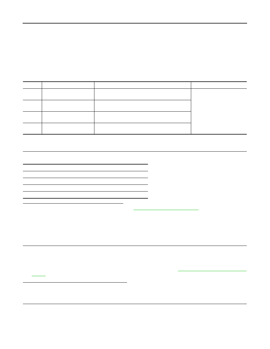
DTC DETECTION LOGIC
DTC CONFIRMATION PROCEDURE
1.
CHECK SELF-DIAGNOSIS RESULTS
Check the self-diagnosis results.
Is above displayed on the self-diagnosis display?
YES
>> Proceed to diagnosis procedure. Refer to
.
NO
>> INSPECTION END
Diagnosis Procedure
INFOID:0000000001090898
INSPECTION PROCEDURE
1.
CHECK CONNECTOR
1.
Turn ignition switch OFF.
2.
Disconnect ABS actuator and electric unit (control unit) connector.
3.
Check terminal for deformation, disconnection, looseness, and so on. If any malfunction is found, repair or
replace terminal.
4.
Reconnect connector and then perform the self-diagnosis. Refer to
.
Is any item indicated on the self-diagnosis display?
YES
>> GO TO 2.
NO
>> Poor connection of connector terminal. Replace or repair connector.
2.
CHECK ACTUATOR RELAY POWER SUPPLY CIRCUIT
1.
Turn ignition switch OFF.
2.
Disconnect ABS actuator and electric unit (control unit) connector.
3.
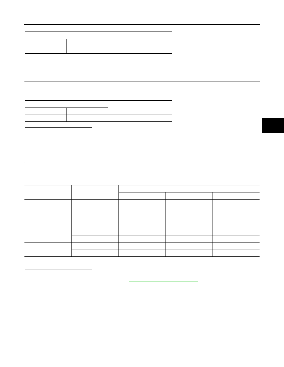
Check voltage between ABS actuator and electric unit (control unit) harness connector terminal and
ground.
DTC
Display item
Malfunction detected condition
Possible cause
C1121
FR LH OUT ABS SOL
When the control unit detects a malfunction in the front
LH outlet solenoid circuit.
ABS actuator and electric unit
(control unit)
C1123
FR RH OUT ABS SOL
When the control unit detects a malfunction in the front
RH outlet solenoid circuit.
C1125
RR LH OUT ABS SOL
When the control unit detects a malfunction in the rear LH
outlet solenoid circuit.
C1127
RR RH OUT ABS SOL
When the control unit detects a malfunction in the rear
RH outlet solenoid circuit.
Self-diagnosis results
FR LH OUT ABS SOL
FR RH OUT ABS SOL
RR LH OUT ABS SOL
RR RH OUT ABS SOL
C1121, C1123, C1125, C1127 OUT ABS SOL
BRC-43
< COMPONENT DIAGNOSIS >
[ABS]
C
D
E
G
H
I
J
K
L
M
A
B
BRC
N
O
P
Is the inspection result normal?
YES
>> GO TO 3.
NO
>> Repair or replace malfunctioning components.
3.
CHECK ACUATOR RELAY GROUND CIRCUIT
Check continuity between ABS actuator and electric unit (control unit) harness connector terminals and
ground.
Is the inspection result normal?
YES
>> Replace ABS actuator and electric unit (control unit).
NO
>> Repair or replace malfunctioning components.
Component Inspection
INFOID:0000000001090899
1.
CHECK ACTIVE TEST
1.
Select each test menu item on ”ACTIVE TEST“.
2.
On the display, touch “UP”, “KEEP”, and “DOWN”, and check that the system operates as shown in the
table below.
*: ON for 1 to 2 seconds after the touch, and then OFF.
Is the inspection result normal?
YES
>> INSPECTION END
NO
>> Go to diagnosis procedure. Refer to
ABS actuator and electric unit (control unit)
—
Voltage
Connector
Terminal
E34
3
Ground
Battery voltage
ABS actuator and electric unit (control unit)
—
Continuity
Connector
Terminal
E34
1, 4
Ground
Existed
Test item
Display item
Display
UP
KEEP
DOWN
FR RH SOL
FR RH IN SOL
OFF
ON
ON
FR RH OUT SOL
OFF
OFF
ON*
FR LH SOL
FR LH IN SOL
OFF
ON
ON
FR LH OUT SOL
OFF
OFF
ON*
RR RH SOL
RR RH IN SOL
OFF
ON
ON
RR RH OUT SOL
OFF
OFF
ON*
RR LH SOL
RR LH IN SOL
OFF
ON
ON
RR LH OUT SOL
OFF
OFF
ON*
BRC-44
< COMPONENT DIAGNOSIS >
[ABS]
U1000 CAN COMM CIRCUIT
U1000 CAN COMM CIRCUIT
Description
INFOID:0000000000925048
CAN (Controller Area Network) is a serial communication line for real time application. It is an on-vehicle mul-
tiplex communication line with high data communication speed and excellent error detection ability. Many elec-
tronic control units are equipped onto a vehicle, and each control unit shares information and links with other
control units during operation (not independent). In CAN communication, control units are connected with 2
communication lines (CAN-H line, CAN-L line) allowing a high rate of information transmission with less wiring.
Each control unit transmits/receives data but selectively reads required data only.
DTC Logic
INFOID:0000000000925049
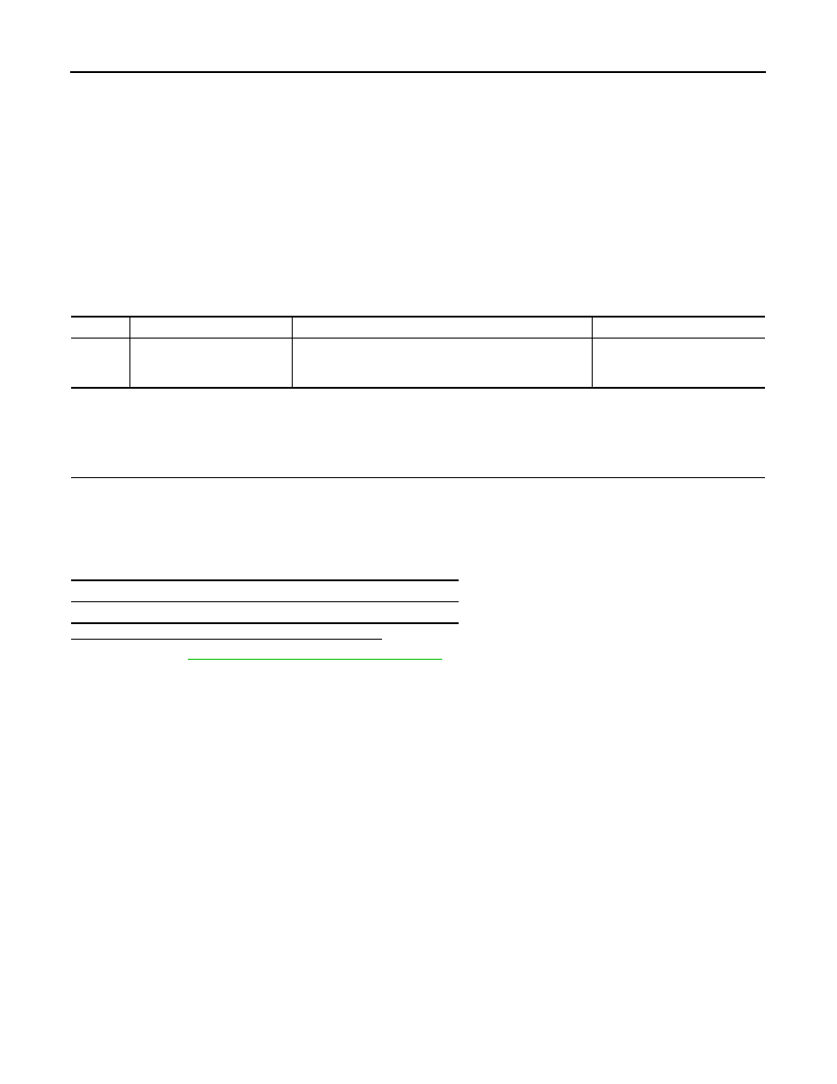
DTC DETECTION LOGIC
Diagnosis Procedure
INFOID:0000000000925050
INSPECTION PROCEDURE
1.
CHECK CONNECTOR
1.
Turn ignition switch OFF.
2.
Disconnect ABS actuator and electric unit (control unit) connector.
3.
Check terminal for deformation, disconnection, looseness, and so on. If any malfunction is found, repair or
replace terminal.
4.
Reconnect connector and perform self-diagnosis.
Is above displayed on the self-diagnosis display?
YES
>> Go to
LAN-46, "Trouble Diagnosis Flow Chart"
.
NO
>> INSPECTION END
DTC
Display item
Malfunction detected condition
Possible cause
U1000
CAN COMM CIRCUIT
When ABS actuator and electric unit (control unit) is not
transmitting or receiving CAN communication signal for 2
seconds or more.
• CAN communication line
• ABS actuator and electric unit
(control unit)
Self-diagnosis results
CAN COMM CIRCUIT
BRAKE FLUID LEVEL SWITCH
BRC-45
< COMPONENT DIAGNOSIS >
[ABS]
C
D
E
G
H
I
J
K
L
M
A
B
BRC
N
O
P
BRAKE FLUID LEVEL SWITCH
Description
INFOID:0000000000925043
The brake fluid level switch converts the brake fluid level to an electric signal and transmits it to the ABS actu-
ator and electric unit (control unit).
Component Function Check
INFOID:0000000000925730
1.
CHECK BRAKE FLUID LEVEL SWITCH OPERATION
Operate the brake fluid level switch. Then check that the brake warning lamp in the combination meter turns
ON/OFF correctly.
Is the inspection result normal?
YES
>> INSPECTION END
NO
>> Go to diagnosis procedure. Refer to
Diagnosis Procedure
INFOID:0000000000925045
INSPECTION PROCEDURE
1.
CHECK CONNECTOR
1.
Turn ignition switch OFF.
2.
Disconnect brake fluid level switch connector and combination meter connector.
3.
Check terminal for deformation, disconnection, looseness, and so on. If any malfunction is found, repair or
replace terminal.
4.
Reconnect connectors and then perform component function check. Refer to
Is the inspection result normal?
YES
>> Poor connection of connector terminal. Replace or repair connector.
NO
>> GO TO 2.
2.
CHECK BRAKE FLUID LEVEL SWITCH
1.
Turn ignition switch OFF.
2.
Disconnect brake fluid level switch connector.
3.
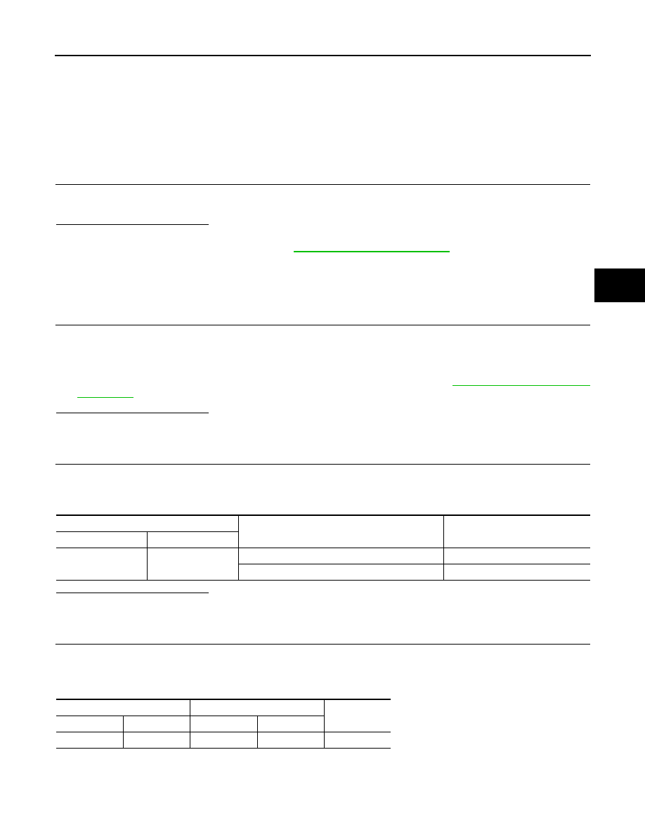
Check continuity between brake fluid level switch connector terminals.
Is the inspection result normal?
YES
>> GO TO 3.
NO
>> Brake fluid level switch is malfunction. Replace reservoir tank.
3.
CHECK BRAKE FLUID LEVEL SWITCH CIRCUIT
1.
Disconnect combination meter connector.
2.
Check continuity between brake fluid level switch harness connector terminals and combination meter
harness connector terminal and/or ground.
Brake fluid level switch
Condition
Continuity
Connector
Terminal
E37
1 – 2
When brake fluid is full in the reservoir tank.
Not existed
When brake fluid is empty in the reservoir tank.
Existed
Combination meter
Brake fluid level switch
Continuity
Connector
Terminal
Connector
Terminal
M34
27
E37
1
Existed
Нет комментариевНе стесняйтесь поделиться с нами вашим ценным мнением.
Текст