Nissan Qashqai (2007-2010). Manual — part 710
BRC-38
< COMPONENT DIAGNOSIS >
[ABS]
C1116 STOP LAMP SWITCH
C1116 STOP LAMP SWITCH
Description
INFOID:0000000000925000
The stop lamp switch transmits the stop lamp switch signal (ON/OFF) to the ABS actuator and electric unit
(control unit).
DTC Logic
INFOID:0000000000925001
DTC DETECTION LOGIC
DTC CONFIRMATION PROCEDURE
1.
CHECK SELF-DIAGNOSIS RESULTS
Check the self-diagnosis results.
Is above displayed on the self-diagnosis display?
YES
>> Proceed to diagnosis procedure. Refer to
.
NO
>> INSPECTION END
Diagnosis Procedure
INFOID:0000000000925002
INSPECTION PROCEDURE
1.
CHECK STOP LAMP ILLUMINATE
Press brake pedal and check stop lamp illuminate.
Is the inspection result normal?
YES
>> GO TO 2.
NO
>> Repair or replace malfunctioning components.
2.
CHECK CONNECTOR
1.
Turn ignition switch OFF.
2.
Disconnect ABS actuator and electric unit (control unit) connector.
3.
Disconnect stop lamp switch connector.
4.
Check terminal for deformation, disconnection, looseness, and so on. If any malfunction is found, repair or
replace terminal.
5.
Reconnect connectors securely.
6.
Start engine.
7.
Repeat pumping brake pedal carefully several times, and perform self-diagnosis.
Is any item indicated on the self-diagnosis display?
YES
>> GO TO 3.
NO
>> Poor connection of connector terminal. Replace or repair connector.
3.
CHECK STOP LAMP SWITCH
1.
Turn ignition switch OFF.
2.
Disconnect stop lamp switch connector.
3.
Check continuity between stop lamp switch connector terminals.
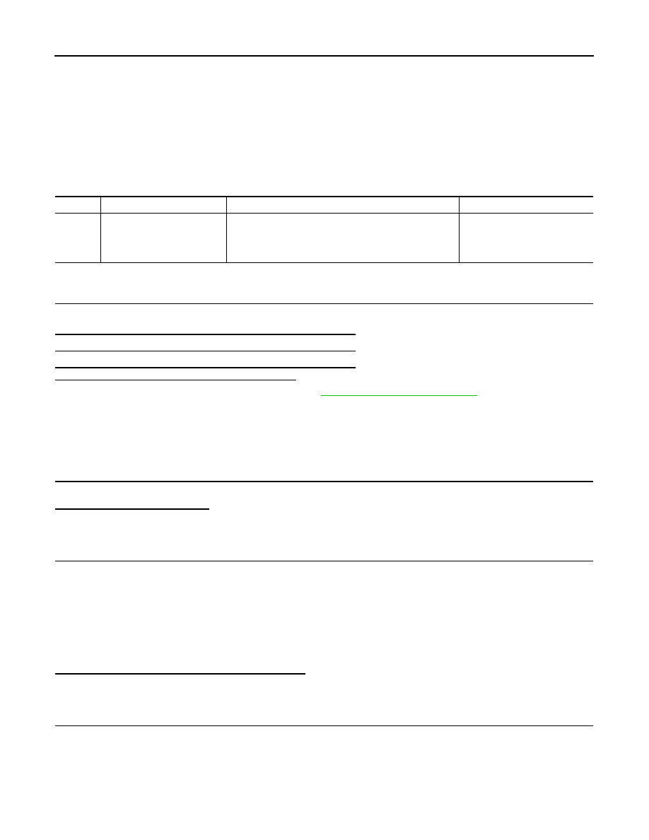
DTC
Display item
Malfunction detected condition
Possible cause
C1116
STOP LAMP SW
When stop lamp switch circuit is open.
• Harness or connector
• Stop lamp switch
• ABS actuator and electric unit
(control unit)
Self-diagnosis results
STOP LAMP SW
C1116 STOP LAMP SWITCH
BRC-39
< COMPONENT DIAGNOSIS >
[ABS]
C
D
E
G
H
I
J
K
L
M
A
B
BRC
N
O
P
Is the inspection result normal?
YES
>> GO TO 4.
NO
>> Replace stop lamp switch.
4.
CHECK STOP LAMP SWITCH CIRCUIT
1.
Disconnect ABS actuator and electric unit (control unit) connector.
2.
Connect stop lamp switch connector.
3.
Check voltage between ABS actuator and electric unit (control unit) harness connector terminal and
ground.
Is the inspection result normal?
YES
>> Replace ABS actuator and electric unit (control unit).
NO
>> Repair or replace malfunctioning components.
Component Inspection
INFOID:0000000000925003
1.
CHECK STOP LAMP SWITCH
1.
Turn ignition switch OFF.
2.
Disconnect stop lamp switch connector.
3.
Check continuity between stop lamp switch connector terminals.
Is the inspection result normal?
YES
>> INSPECTION END
NO
>> Replace stop lamp switch.
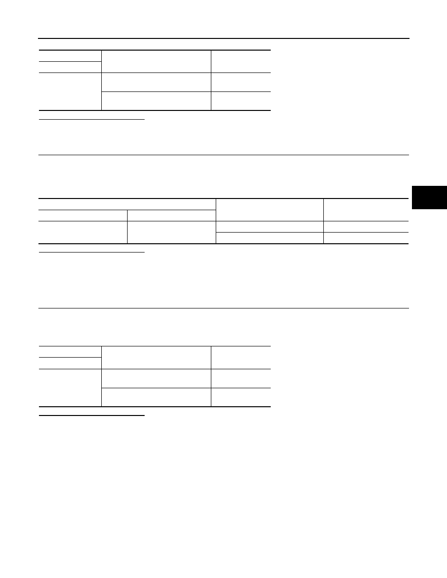
Stop lamp switch
Condition
Continuity
Terminal
1
−
2
Release stop lamp switch
(When brake pedal is depressed.)
Existed
Push stop lamp switch
(When brake pedal is released.)
Not existed
ABS actuator and electric unit (control unit)
Condition
Voltage
Connector
Terminal
E34
20
Brake pedal is depressed
Battery voltage
Brake pedal is released
Approx. 0 V
Stop lamp switch
Condition
Continuity
Terminal
1
−
2
Release stop lamp switch
(When brake pedal is depressed.)
Existed
Push stop lamp switch
(When brake pedal is released.)
Not existed
BRC-40
< COMPONENT DIAGNOSIS >
[ABS]
C1120, C1122, C1124, C1126 IN ABS SOL
C1120, C1122, C1124, C1126 IN ABS SOL
Description
INFOID:0000000000925005
The solenoid valve increases, holds or decreases the fluid pressure of each brake caliper according to the sig-
nals transmitted by the ABS actuator and electric unit (control unit).
DTC Logic
INFOID:0000000000925006
DTC DETECTION LOGIC
DTC CONFIRMATION PROCEDURE
1.
CHECK SELF-DIAGNOSIS RESULTS
Check the self-diagnosis results.
Is above displayed on the self-diagnosis display?
YES
>> Proceed to diagnosis procedure. Refer to
.
NO
>> INSPECTION END
Diagnosis Procedure
INFOID:0000000000925007
INSPECTION PROCEDURE
1.
CHECK CONNECTOR
1.
Turn ignition switch OFF.
2.
Disconnect ABS actuator and electric unit (control unit) connector.
3.
Check terminal for deformation, disconnection, looseness, and so on. If any malfunction is found, repair or
replace terminal.
4.
Reconnect connector and then perform the self-diagnosis. Refer to
.
Is any item indicated on the self-diagnosis display?
YES
>> GO TO 2.
NO
>> Poor connection of connector terminal. Replace or repair connector.
2.
CHECK ACTUATOR RELAY POWER SUPPLY CIRCUIT
1.
Turn ignition switch OFF.
2.
Disconnect ABS actuator and electric unit (control unit) connector.
3.
Check voltage between ABS actuator and electric unit (control unit) harness connector terminal and
ground.
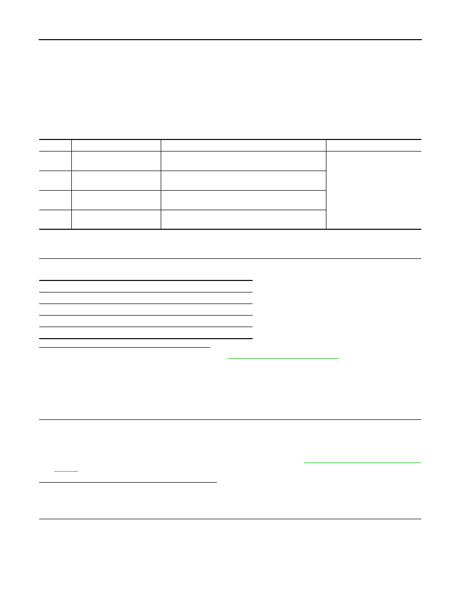
DTC
Display item
Malfunction detected condition
Possible cause
C1120
FR LH IN ABS SOL
When the control unit detects a malfunction in the front
LH inlet solenoid circuit.
ABS actuator and electric unit
(control unit)
C1122
FR RH IN ABS SOL
When the control unit detects a malfunction in the front
RH inlet solenoid circuit.
C1124
RR LH IN ABS SOL
When the control unit detects a malfunction in the rear LH
inlet solenoid circuit.
C1126
RR RH IN ABS SOL
When the control unit detects a malfunction in the rear
RH inlet solenoid circuit.
Self-diagnosis results
FR LH IN ABS SOL
FR RH IN ABS SOL
RR LH IN ABS SOL
RR RH IN ABS SOL
C1120, C1122, C1124, C1126 IN ABS SOL
BRC-41
< COMPONENT DIAGNOSIS >
[ABS]
C
D
E
G
H
I
J
K
L
M
A
B
BRC
N
O
P
Is the inspection result normal?
YES
>> GO TO 3.
NO
>> Repair or replace malfunctioning components.
3.
CHECK ACUATOR RELAY GROUND CIRCUIT
Check continuity between ABS actuator and electric unit (control unit) harness connector terminals and
ground.
Is the inspection result normal?
YES
>> Replace ABS actuator and electric unit (control unit).
NO
>> Repair or replace malfunctioning components.
Component Inspection
INFOID:0000000000925008
1.
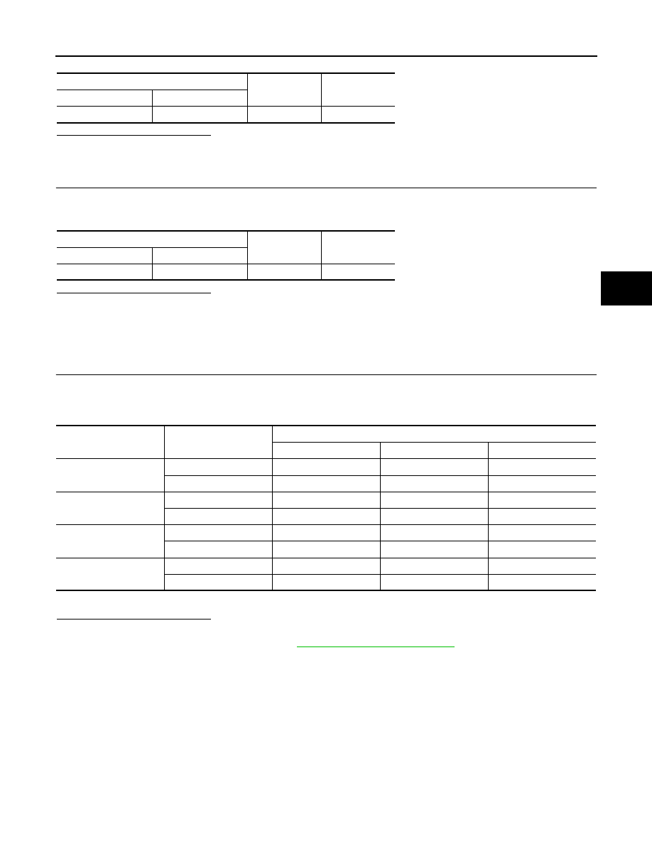
CHECK ACTIVE TEST
1.
Select each test menu item on ”ACTIVE TEST“.
2.
On the display, touch “UP”, “KEEP”, and “DOWN”, and check that the system operates as shown in the
table below.
*: ON for 1 to 2 seconds after the touch, and then OFF.
Is the inspection result normal?
YES
>> INSPECTION END
NO
>> Go to diagnosis procedure. Refer to
ABS actuator and electric unit (control unit)
—
Voltage
Connector
Terminal
E34
3
Ground
Battery voltage
ABS actuator and electric unit (control unit)
—
Continuity
Connector
Terminal
E34
1, 4
Ground
Existed
Test item
Display item
Display
UP
KEEP
DOWN
FR RH SOL
FR RH IN SOL
OFF
ON
ON
FR RH OUT SOL
OFF
OFF
ON*
FR LH SOL
FR LH IN SOL
OFF
ON
ON
FR LH OUT SOL
OFF
OFF
ON*
RR RH SOL
RR RH IN SOL
OFF
ON
ON
RR RH OUT SOL
OFF
OFF
ON*
RR LH SOL
RR LH IN SOL
OFF
ON
ON
RR LH OUT SOL
OFF
OFF
ON*
Нет комментариевНе стесняйтесь поделиться с нами вашим ценным мнением.
Текст