Nissan Qashqai (2007-2010). Manual — part 708
BRC-30
< COMPONENT DIAGNOSIS >
[ABS]
C1111 ABS MOTOR, MOTOR RELAY SYSTEM
4.
Reconnect ABS actuator and electric unit (control unit) connector.
Is the inspection result normal?
YES
>> GO TO 3.
NO
>> Repair or replace malfunctioning components.
3.
ABS POWER SUPPLY CHECK (UNDER LOAD CONDITIONS)
Use 12V lamp (normal rating 10 to 20W) connected between E34 terminals 1 and 2. With ignition switch ON
check bulb illuminates correctly.
Is the inspection result normal?
YES
>> GO TO 4.
NO
>> Check both power supply and ground circuit.
4.
CHECK ABS ACTUATOR AND ELECTRIC UNIT (CONTROL UNIT) GROUND CIRCUIT
1.
Turn ignition switch OFF.
2.
Disconnect ABS actuator and electric unit (control unit) connector.
3.
Check continuity between ABS actuator and electric unit (control unit) harness connector terminals and
ground.
Is the inspection result normal?
YES
>> Replace ABS actuator and electric unit (control unit).
NO
>> Repair or replace malfunctioning components. (Check ABS each bolt for tightness and corrosion).
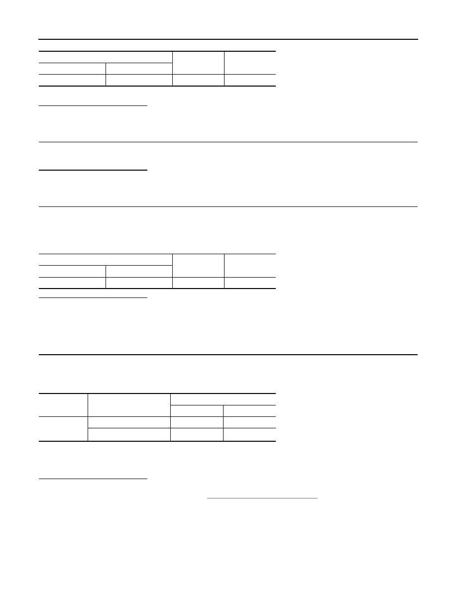
Component Inspection
INFOID:0000000000924988
1.
CHECK ACTIVE TEST
1.
On “ACTIVE TEST”, select “ABS MOTOR”.
2.
Touch “ON” and “OFF” on screen. Make sure motor relay and actuator relay operates as shown in table
below.
NOTE:
A brief moment of ON/OFF condition occurs every 20 seconds after ignition switch turned ON. This is not malfunction because it is
an operation for checking.
Is the inspection result normal?
YES
>> INSPECTION END
NO
>> Go to diagnosis procedure. Refer to
ABS actuator and electric unit (control unit)
—
Voltage
Connector
Terminal
E34
2
Ground
Battery voltage
ABS actuator and electric unit (control unit)
—
Continuity
Connector
Terminal
E34
1, 4
Ground
Existed
Test item
Display item
Display
ON
OFF
ABS MOTOR
MOTOR RELAY
ON
OFF
ACTUATOR RLY
NOTE
ON
ON
C1113 G SENSOR
BRC-31
< COMPONENT DIAGNOSIS >
[ABS]
C
D
E
G
H
I
J
K
L
M
A
B
BRC
N
O
P
C1113 G SENSOR
Description
INFOID:0000000000936456
G sensor detects G affecting the vehicle, and transmits the data to the ABS actuator and electric unit (control
unit) as an analog voltage signal.
DTC Logic
INFOID:0000000000936457
DTC DETECTION LOGIC
DTC CONFIRMATION PROCEDURE
1.
CHECK SELF-DIAGNOSIS RESULTS
Check the self-diagnosis results.
Is above displayed on the self-diagnosis display?
YES
>> Proceed to diagnosis procedure. Refer to
.
NO
>> INSPECTION END
Diagnosis Procedure
INFOID:0000000000936458
INSPECTION PROCEDURE
1.
CHECK CONNECTOR
1.
Turn ignition switch OFF.
2.
Disconnect ABS actuator and electric unit (control unit) connector.
3.
Disconnect G sensor connector.
4.
Check terminal for deformation, disconnection, looseness, and so on. If any malfunction is found, repair or
replace terminal.
5.
Reconnect connectors and then perform the self-diagnosis. Refer to
.
Is any item indicated on the self-diagnosis display?
YES
>> GO TO 2.
NO
>> Poor connection of connector terminal. Replace or repair connector.
2.
CHECK G SENSOR POWER SUPPLY CIRCUIT
1.
Turn ignition switch OFF.
2.
Disconnect G sensor connector.
3.
Turn ignition switch ON or OFF and check voltage between G sensor harness connector terminal and
ground.
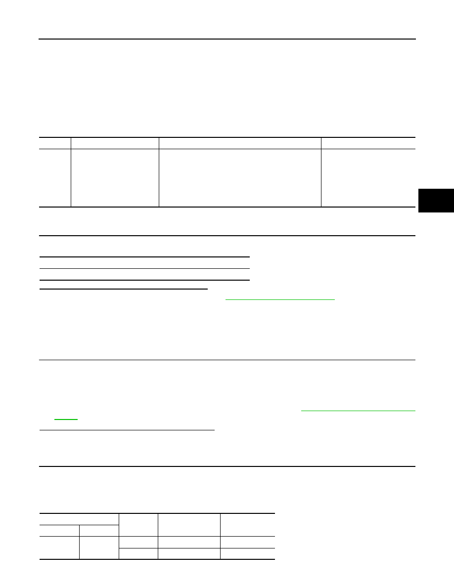
DTC
Display item
Malfunction detected condition
Possible cause
C1113
G SENSOR
G sensor is malfunctioning, or signal line of G sensor is
open or shorted.
• Harness or connector
• ABS actuator and electric unit
(control unit)
• G sensor
• Electrical interference
• Vehicle driven on 4WD rolling
road
Self-diagnosis results
G SENSOR
G sensor
—
Condition
Voltage
Connector
Terminal
M71
3
Ground
Ignition switch: ON
Battery voltage
Ground
Ignition switch: OFF
Approx. 0 V
BRC-32
< COMPONENT DIAGNOSIS >
[ABS]
C1113 G SENSOR
Is the inspection result normal?
YES
>> GO TO 3.
NO
>> Repair or replace malfunctioning components.
3.
CHECK G SENSOR GROUND CIRCUIT
Check continuity between G sensor harness connector terminal and ground.
Is the inspection result normal?
YES
>> GO TO 4.
NO
>> Repair or replace malfunctioning components.
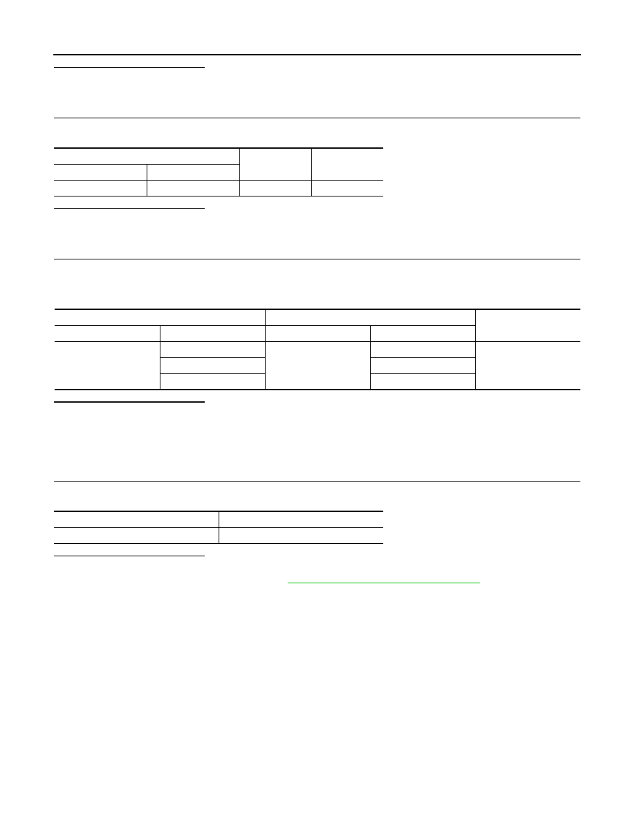
4.
CHECK G SENSOR HARNESS
1.
Disconnect ABS actuator and electric unit (control unit) connector.
2.
Check continuity between G sensor harness connector terminals and ABS actuator and electric unit (con-
trol unit) harness connector terminals.
Is the inspection result normal?
YES
>> Replace G sensor.
NO
>> Repair or replace malfunctioning components.
Component Inspection
INFOID:0000000000936459
1.
CHECK DATA MONITOR
Select “G SENSOR”, in “DATA MONITOR” and check G sensor signal.
Is the inspection result normal?
YES
>> INSPECTION END
NO
>> Go to diagnosis procedure. Refer to
BRC-17, "CONSULT-III Function (ABS)"
.
G sensor
—
Continuity
Connector
Terminal
M71
1
Ground
Existed
ABS actuator and electric unit (control unit)
G sensor
Continuity
Connector
Terminal
Connector
Terminal
E34
14
M71
1
Existed
21
2
24
3
Monitor item
DATA MONITOR
G SENSOR
ON/OFF
C1114 ACTUATOR RELAY SYSTEM
BRC-33
< COMPONENT DIAGNOSIS >
[ABS]
C
D
E
G
H
I
J
K
L
M
A
B
BRC
N
O
P
C1114 ACTUATOR RELAY SYSTEM
Description
INFOID:0000000000924990
Activates or deactivates each solenoid valve according to the signals transmitted by the ABS actuator and
electric unit (control unit).
DTC Logic
INFOID:0000000000924991
DTC DETECTION LOGIC
DTC CONFIRMATION PROCEDURE
1.
CHECK SELF-DIAGNOSIS RESULTS
Check the self-diagnosis results.
Is above displayed on the self-diagnosis display?
YES
>> Proceed to diagnosis procedure. Refer to
.
NO
>> INSPECTION END
Diagnosis Procedure
INFOID:0000000000924992
INSPECTION PROCEDURE
1.
CHECK CONNECTOR
1.
Turn ignition switch OFF.
2.
Disconnect ABS actuator and electric unit (control unit) connector.
3.
Check terminal for deformation, disconnection, looseness, and so on. If any malfunction is found, repair or
replace terminal.
4.
Reconnect connector and then perform the self-diagnosis. Refer to
.
Is any item indicated on the self-diagnosis display?
YES
>> GO TO 2.
NO
>> Poor connection of connector terminal. Replace or repair connector.
2.
CHECK ACTUATOR RELAY POWER SUPPLY CIRCUIT
1.
Turn ignition switch OFF.
2.
Disconnect ABS actuator and electric unit (control unit) connector.
3.
Check voltage between ABS actuator and electric unit (control unit) harness connector terminal and
ground.
4.
Reconnect ABS actuator and electric unit (control unit) connector.
Is the inspection result normal?
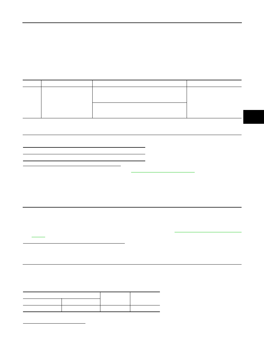
DTC
Display item
Malfunction detected condition
Possible cause
C1114
MAIN RELAY
During the actuator relay operating with OFF, when the
actuator relay turns ON, or when the control line for the
relay is shorted to the ground.
• Harness or connector
• ABS actuator and electric unit
(control unit)
During the actuator relay operating with ON, when the
actuator relay turns ON, or when the control line for the
relay is open.
Self-diagnosis results
MAIN RELAY
ABS actuator and electric unit (control unit)
—
Voltage
Connector
Terminal
E34
3
Ground
Battery voltage
Нет комментариевНе стесняйтесь поделиться с нами вашим ценным мнением.
Текст