Nissan Qashqai (2007-2010). Manual — part 451
P0045 TC BOOST CONTROL SOLENOID VALVE
EC-1323
< COMPONENT DIAGNOSIS >
[K9K]
C
D
E
F
G
H
I
J
K
L
M
A
EC
N
P
O
P0045 TC BOOST CONTROL SOLENOID VALVE
DTC Logic
INFOID:0000000001115054
DTC DETECTION LOGIC
NOTE:
• If the DTC is present:
- Malfunction indicator (Red) lights up.
Diagnosis Procedure
INFOID:0000000001088004
1.
CHECK TURBOCHARGER BOOST CONTROL SOLENOID VALVE POWER SUPPLY CIRCUIT
1.
Turn ignition switch OFF.
2.
Disconnect turbocharger boost control solenoid valve harness connector.
3.
Turn ignition switch ON.
4.
Check the voltage between turbocharger boost control solenoid valve harness connector and ground.
Is the inspection result normal?
YES
>> GO TO 3.
NO
>> GO TO 2.
2.
DETECT MALFUNCTIONING PART
Check the following.
• Harness for open or short between IPDM E/R and turbocharger boost control solenoid valve
• Harness for open or short between ECM and turbocharger boost control solenoid valve
>> Repair open circuit or short to ground or short to power in harness or connectors.
3.
CHECK TURBOCHARGER BOOST CONTROL SOLENOID VALVE OUTPUT SIGNAL CIRCUIT FOR
OPEN AND SHORT
1.
Turn ignition switch OFF.
2.
Disconnect ECM harness connector.
3.
Check the continuity between turbocharger boost control solenoid valve harness connector and ECM har-
ness connector.
4.
Also check harness for short to ground and short to power.
Is the inspection result normal?
YES
>> GO TO 5.
NO
>> GO TO 4.
4.
DETECT MALFUNCTIONING PART
Check the following.
• Harness connector E7, F121
DTC No.
Trouble diagnosis name
Possible cause
P0045
TURBOCHARGER BOOST CONTROL SOLENOID VALVE CIRCUIT
• CO: Open circuit
• CO.0: Open circuit or short circuit to ground
• CC.1: Short circuit to +12V
• Harness or connectors
(The solenoid valve circuit is open or short-
ed.)
• Turbocharger boost control solenoid valve
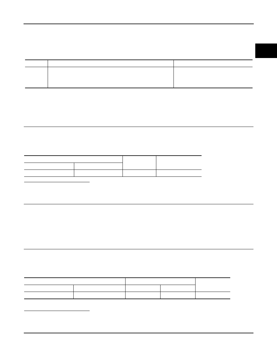
Turbocharger boost control solenoid valve
Ground
Voltage
Connector
Terminal
E55
2
Ground
Battery voltage
Turbocharger boost control solenoid valve
ECM
Continuity
Connector
Terminal
Connector
Terminal
E55
1
F68
52
Existed
EC-1324
< COMPONENT DIAGNOSIS >
[K9K]
P0045 TC BOOST CONTROL SOLENOID VALVE
• Harness for open or short between ECM and turbocharger boost control solenoid valve
>> Repair open circuit or short to ground or short to power in harness or connectors.
5.
CHECK TURBOCHARGER BOOST CONTROL SOLENOID VALVE
EC-1328, "Component Inspection"
.
Is the inspection result normal?
YES
>> GO TO 6.
NO
>> Replace turbocharger boost control solenoid valve.
6.
CHECK INTERMITTENT INCIDENT
GI-39, "Intermittent Incident"
>> INSPECTION END
Component Inspection
INFOID:0000000001088005
1.
CHECK TURBOCHARGER BOOST CONTROL SOLENOID VALVE
1.
Turn ignition switch OFF.
2.
Disconnect turbocharger boost control solenoid valve harness connector.
3.
Check resistance between turbocharger boost control solenoid valve terminals as follows.
Is the inspection result normal?
YES
>> INSPECTION END
NO
>> Replace high pressure supply pump.
Terminals
Resistance
1 and 2
18.9 - 23.1
Ω
[at 23
°
C (73
°
F)]
P0069 TC BOOST SENSOR, BARO SENSOR CORRELATION
EC-1325
< COMPONENT DIAGNOSIS >
[K9K]
C
D
E
F
G
H
I
J
K
L
M
A
EC
N
P
O
P0069 TC BOOST SENSOR, BARO SENSOR CORRELATION
DTC Logic
INFOID:0000000001115055
DTC DETECTION LOGIC
NOTE:
• Conditions for applying the diagnostic procedure to the stored DTCs:
The DTC becomes present after the engine is started.
• If the DTC is present:
- Malfunction indicator (Red) lights up.
Diagnosis Procedure
INFOID:0000000000953026
1.
CHECK GROUND CONNECTIONS
1.
Turn ignition switch OFF.
2.
Check ground connection E17. Refer to Ground inspection in
Is the inspection result normal?
YES
>> GO TO 2.
NO
>> Repair or replace ground connection.
2.
CHECK TUBOCHARGER BOOST SENSOR SUPPLY CIRCUIT
1.
Disconnect turbocharger boost sensor harness connector.
2.
Turn ignition switch ON.
3.
Check the voltage between turbocharger boost sensor connector and ground.
Is the inspection result normal?
YES
>> GO TO 3.
NO
>> Repair open circuit or short to ground or short to power in harness or connectors.
3.
CHECK TUBOCHARGER BOOST SENSOR GROUND CIRCUIT FOR OPEN AND SHORT
1.
Check the continuity between turbocharger boost sensor harness connector and ECM harness connector.
2.
Also check harness for short to ground and short to power.
Is the inspection result normal?
YES
>> GO TO 4.
NO
>> Repair open circuit or short to ground or short to power in harness or connectors.
4.
CHECK TUBOCHARGER BOOST SENSOR INPUT SIGNAL CIRCUIT FOR OPEN AND SHORT
1.
Check the continuity between turbocharger boost sensor harness connector and ECM harness connector.
DTC No.
Trouble diagnosis name
Possible cause
P0069
TURBOCHARGER BOOST SENSOR - BAROMETRIC PRESSURE SENSOR
CORRELATION
• 1.DEF: Signal outside lower level
• 2.DED: Signal outside upper level
• Harness or connectors
(Turbocharger boost sensor)
• Turbocharger boost sensor
• Barometric pressure sensor
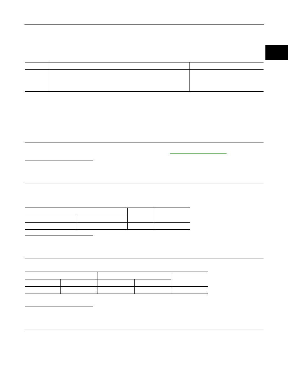
Turbocharger boost sensor
Ground
Voltage
Connector
Terminal
F91
1
Ground
Approx. 5V
Turbocharger boost sensor
ECM
Continuity
Connector
Terminal
Connector
Terminal
F91
2
F85
43
Existed
EC-1326
< COMPONENT DIAGNOSIS >
[K9K]
P0069 TC BOOST SENSOR, BARO SENSOR CORRELATION
2.
Also check harness for short to ground and short to power.
Is the inspection result normal?
YES
>> GO TO 5.
NO
>> Repair open circuit or short to ground or short to power in harness or connectors.
5.
CHECK TUBOCHARGER BOOST SENSOR
EC-1364, "Component Inspection"
.
Is the inspection result normal?
YES
>> GO TO 6.
NO
>> Replace turbocharger boost sensor.
6.
REPLACE ECM
1.
Perform
EC-1273, "ADDITIONAL SERVICE WHEN REPLACING CONTROL UNIT : Special Repair
.
2.
Perform EGR volume control valve closed position learning. Refer to
TROL VALVE CLOSED POSITION LEARNING : Special Repair Requirement"
>> INSPECTION END
Component Inspection
INFOID:0000000001088007
1.
CHECK TURBOCHARGER BOOST SENSOR-I
1.
Turn ignition switch OFF.
2.
Remove turbocharger boost sensor with its harness connected.
3.
Turn ignition switch ON.
4.
Select “DATA MONITOR” mode with CONSULT-III.
5.
Check “BOOST_PRESS” and “ATOMOS_PRESS” indication.
If the value is not very close to “ATOMOS_PRESS”, maximum pressure difference between
“ATOMOS_PRESS” and “BOOST_PRESS” with the ignition switch ON (engine stop) =
±
50 mbar?
YES
>> GO TO 2.
NO
>> Replace turbocharger boost sensor.
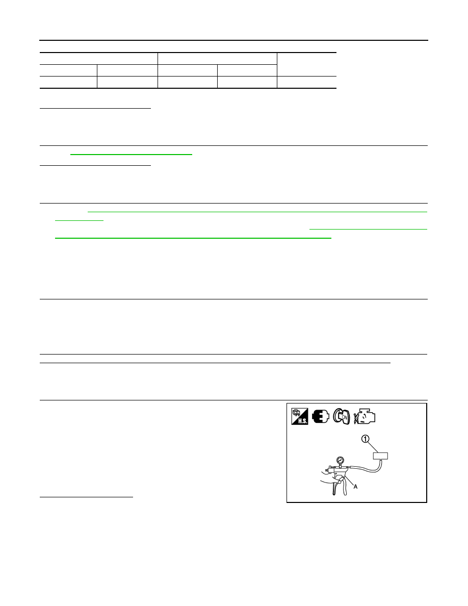
2.
CHECK TURBOCHARGER BOOST SENSOR-II
1.
Use pump to apply turbocharger boost sensor as shown in the
figure.
2.
Apply a pressure of between 10kPa(0.100 bar, 0.102 kg/cm
2
,
1.5 psi) - 13kPa(0.130 bar, 0.133 kg/cm
2
, 1.9 psi) [maximum
pressure to be applied: 13kPa(0.130 bar, 0.133 kg/cm
2
, 1.9
psi)].
3.
Select “DATA MONITOR” mode with CONSULT-III.
4.
Check “BOOST_PRESS” indication with that given by the vac-
uum pump.
If there is no discrepancy?
YES
>> INSPECTION END
NO
>> Replace turbocharger boost sensor.
Turbocharger boost sensor
ECM
Continuity
Connector
Terminal
Connector
Terminal
F91
3
F85
44
Existed
JMBIA0433ZZ
Нет комментариевНе стесняйтесь поделиться с нами вашим ценным мнением.
Текст