Nissan Qashqai (2007-2010). Manual — part 532
CONTROL LINKAGE
TM-63
< ON-VEHICLE REPAIR >
[6MT: RS6F94R]
C
E
F
G
H
I
J
K
L
M
A
B
TM
N
O
P
CONTROL LINKAGE
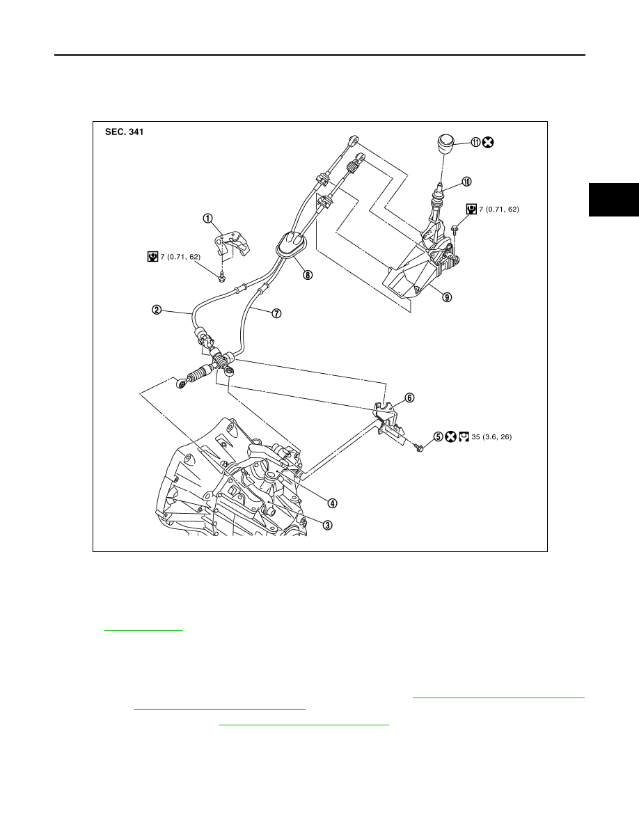
Exploded View
INFOID:0000000001070330
Removal and Installation
INFOID:0000000001070368
REMOVAL
1.
Remove the air cleaner case and air duct (inlet) or air ducts. Refer to
EM-144, "Removal and Installation"
(MR20DE),
EM-265, "Removal and Installation"
(K9K).
2.
Remove the battery. Refer to
PG-118, "Removal and Installation"
.
1.
Bracket
2.
Shift cable
3.
Selector lever
4.
Shifter lever
5.
Tapping bolt
6.
Cable mounting bracket
7.
Select cable
8.
Grommet
9.
Control device assembly
10. Control lever
11.
Control lever knob
Refer to
for the symbols in the figure.
JPDIC0058GB
TM-64
< ON-VEHICLE REPAIR >
[6MT: RS6F94R]
CONTROL LINKAGE
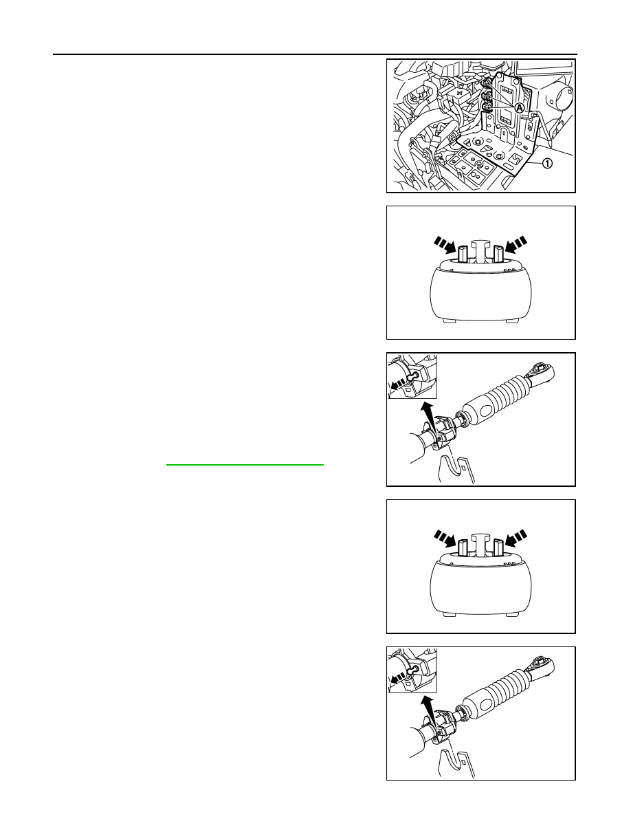
3.
Disconnect connectors (A) and then remove bracket (1).
4.
While pressing the lock of the select cable in the direction of the
arrow shown in the figure, remove the select cable from the
selector lever.
5.
While pressing the lock of the shift cable in the direction of the
arrow shown in the figure, remove the shift cable from the shifter
lever.
6.
While pulling the lock of the select cable in the direction of the
arrow shown in the figure, remove the select cable from the
cable mounting bracket.
7.
While pulling the lock of the shift cable in the direction of the
arrow shown in the figure, remove the shift cable from the cable
mounting bracket.
8.
Remove the control lever knob.
9.
Remove console finisher assembly and the center console
assembly. Refer to
IP-18, "Removal and Installation"
.
10. Shift the control lever to the neutral position.
11. While pressing the lock of the select cable in the direction of the
arrow shown in the figure, remove the select cable from the con-
trol device assembly.
12. While pressing the lock of the shift cable in the direction of the
arrow shown in the figure, remove the shift cable from the con-
trol device assembly.
13. While pulling the lock of the select cable in the direction of the
arrow shown in the figure, remove the select cable from the con-
trol device assembly.
14. While pulling the lock of the shift cable in the direction of the
arrow shown in the figure, remove the shift cable from the con-
trol device assembly.
15. Remove the control device assembly.
16. Remove the heat plate.
17. Remove the bracket.
JPDIA0240ZZ
JPDIC0066ZZ
JPDIC0067ZZ
JPDIC0066ZZ
JPDIC0067ZZ
CONTROL LINKAGE
TM-65
< ON-VEHICLE REPAIR >
[6MT: RS6F94R]
C
E
F
G
H
I
J
K
L
M
A
B
TM
N
O
P
18. Remove the grommet and then remove the shift cable and select cable from the vehicle.
INSTALLATION
Note the following, and install in the reverse order of removal.
• Shift the control lever to the neutral position.
• Securely assemble each cable and the selector lever and shifter lever.
• Securely assemble each cable and the cable mounting bracket.
• Securely assemble each cable and the control device assembly.
• Make sure that the claws of grommet are in contact with the floor.
• Be careful about the installation direction and push the control lever knob into the control lever.
CAUTION:
Never reuse control lever knob.
• Tapping work for tapping bolt is not applied to new clutch housing. Do not perform tapping by other than
screwing tapping bolt because tapping is formed by screwing tapping bolt into clutch housing.
CAUTION:
Never reuse tapping bolt.
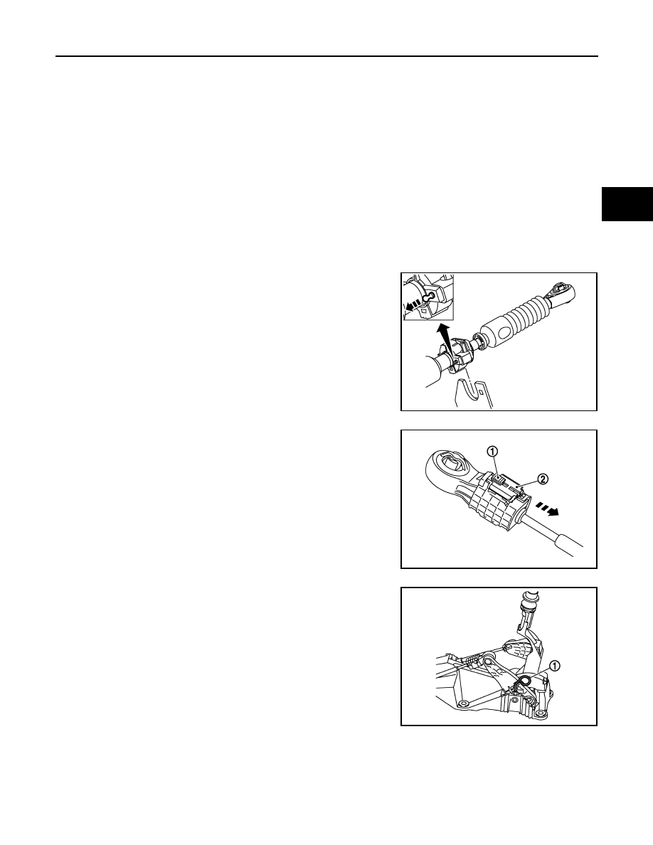
Install the select cable (the control device assembly side) with the following procedure.
1.
While pulling the lock of the select cable in the direction of the
arrow shown in the figure, install the select cable to the control
device assembly.
2.
Slide the lock (1) of the select cable in the direction of the arrow
as shown in the figure to pull up the stopper (2) of the select
cable.
3.
Install the end of the select cable to the pin of the control device
assembly.
4.
Install the lever stopper pin (1) or a pin [3 mm (0.12 in) dia.] to
the control device assembly.
CAUTION:
Select cable cannot be adjusted accurately without a use of
a lever stopper pin or a pin [3 mm (0.12 in) dia.].
NOTE:
A lever stopper pin is not included in control device assembly.
Therefore, if the control device assembly is not replaced, pre-
pare a pin [3 mm (0.12 in) dia.].
5.
Check that the control lever does not move in the direction of the
select. If it moves, repeat step 3.
6.
Shift the control lever to 4th gear position.
JPDIC0067ZZ
JPDIC0064ZZ
JPDIC0069ZZ
TM-66
< ON-VEHICLE REPAIR >
[6MT: RS6F94R]
CONTROL LINKAGE
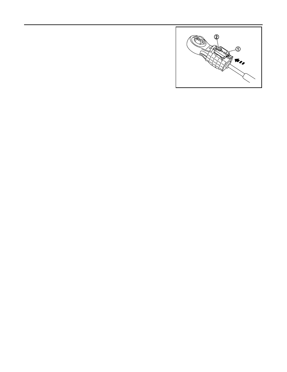
7.
With the stopper (1) of the select cable pressed into all the way,
slide lock (2) of the select cable all the way in the direction of the
arrow.
8.
Remove the lever stopper pin or a pin [3 mm (0.12 in) dia.] from
the control device assembly.
9.
Shift the control lever to each gear position to check that there is
no bindings. If any, repeat step 3.
Inspection
INFOID:0000000001070332
After installing, confirm the following items:
• When the control lever is shifted to 1st-2nd side and 5th-6th side, confirm the control lever returns to neutral
position smoothly.
• When the control lever is shifted to each position, make sure there is no binding or disconnection in each
boot.
JPDIC0065ZZ
Нет комментариевНе стесняйтесь поделиться с нами вашим ценным мнением.
Текст