Nissan Qashqai (2007-2010). Manual — part 2003
CHASSIS MAINTENANCE
MA-51
< ON-VEHICLE MAINTENANCE >
C
D
E
F
G
H
I
J
K
L
M
B
MA
N
O
A
HEADLAMP AIMING ADJUSTMENT (HALOGEN TYPE - LHD) : Aiming Adjustment
Procedure
INFOID:0000000001116173
1.
Place the screen.
NOTE:
• Stop the vehicle at the perpendicular angle to the wall.
• Set the screen perpendicularly to the ground.
2.
Face the vehicle squarely toward the screen and make the distance between the headlamp center and
the screen 10 m (32.8 ft).
3.
Start the engine and illuminate the headlamp (LO).
NOTE:
Block light from the headlamp that is not being adjusted with a thick fabric or another object, so that it
does not reach the adjustment screen.
CAUTION:
Never cover lens surface with tape, etc. because it is made from plastic.
4.
Use the aiming adjustment screw to adjust the elbow point projected by the low beams on the screen, so
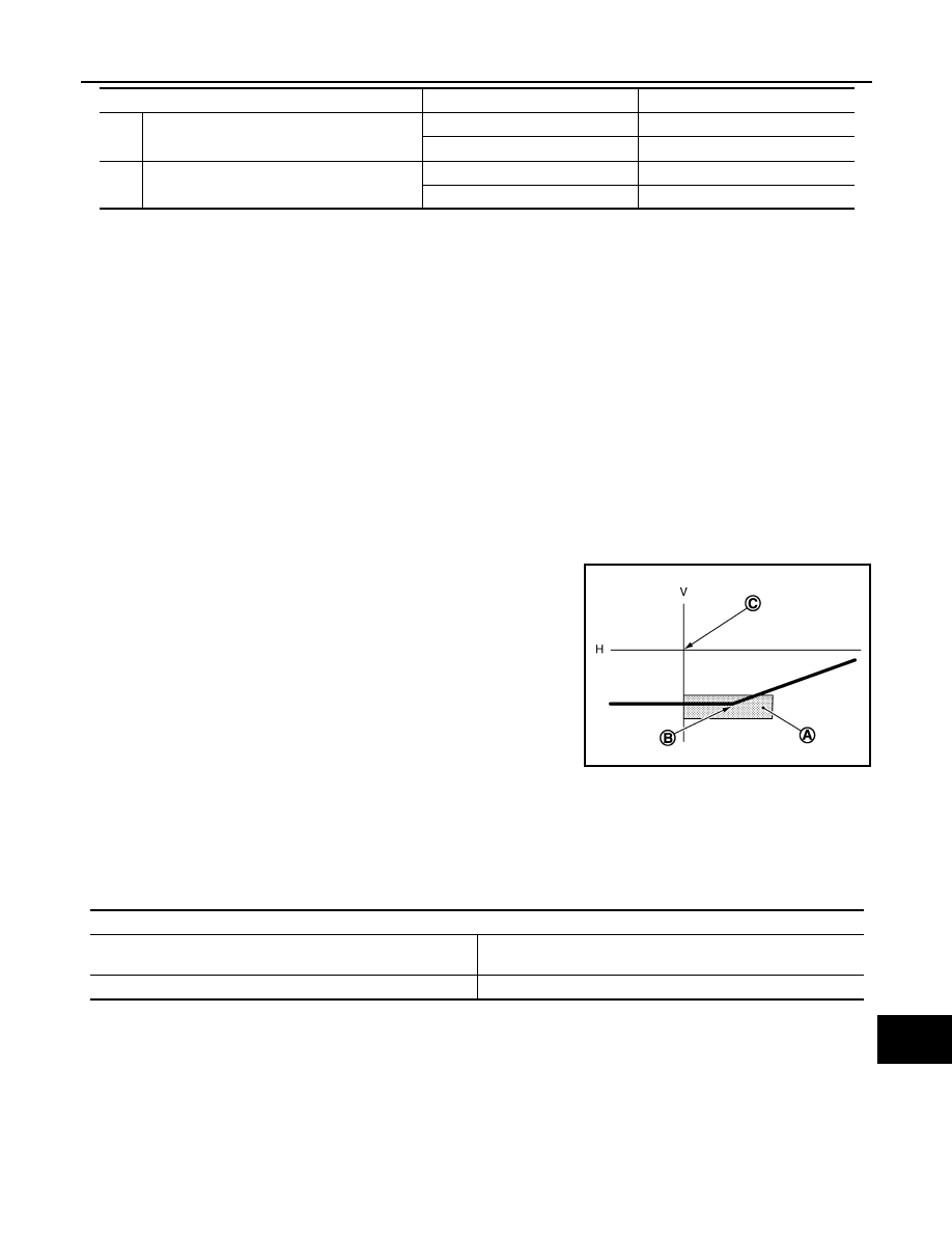
that it is within the aiming adjustment area.
Low beam distribution on the screen
Unit: mm (in)
C
Headlamp LH (INSIDE/OUTSIDE)
Clockwise
INSIDE
Counterclockwise
OUTSIDE
D
Headlamp LH (UP/DOWN)
Clockwise
UP
Counterclockwise
DOWN
Adjustment screw
Screw driver rotation
Facing direction
JSLIA0030ZZ
A.
Aiming adjustment area
B.
Elbow point
C.
Headlamp center
H.
Horizontal center line of headlamp
V.
Vertical center line of headlamp
Aiming adjustment area
Vertical direction (Y)
(Lower side from headlamp center height)
Lateral direction (X)
(Right side from headlamp centerline)
100 – 124 (3.94 – 4.88)
Within 120 (4.72)

MA-52
< ON-VEHICLE MAINTENANCE >
CHASSIS MAINTENANCE
HEADLAMP AIMING ADJUSTMENT (HALOGEN TYPE - RHD)
HEADLAMP AIMING ADJUSTMENT (HALOGEN TYPE - RHD) : Description
INFOID:0000000001116242
PREPARATION BEFORE ADJUSTING
NOTE:
• For details, refer to the regulations in your own country.
• Perform aiming if the vehicle front body has been repaired and/or the headlamp assembly has been
replaced.
Before performing aiming adjustment, check the following.
• Adjust the tire pressure to the specification.
• Fill with fuel, engine coolant and each oil.
• Maintain the unloaded vehicle condition. (Remove luggage from the passenger compartment and the lug-
gage room.)
NOTE:
Do not remove the temporary tire, jack and on-vehicle tool.
• Wipe out dirt on the headlamp.
CAUTION:
Never use organic solvent (thinner, gasoline etc.)
• Ride alone on the driver seat.
• Headlamp aiming switch sets to “0”.
AIMING ADJUSTMENT SCREW
C.
Vertical center line of headlamp H.
Horizontal center line of headlamp
L.
Distance from headlamp center to screen
X.
Aiming adjustment area
(lateral)
Y.
Aiming adjustment area
(Vertical)
Distance from headlamp center to screen (L)
: 10 m (32.8 ft)
JSLIA0031ZZ
CHASSIS MAINTENANCE
MA-53
< ON-VEHICLE MAINTENANCE >
C
D
E
F
G
H
I
J
K
L
M
B
MA
N
O
A
HEADLAMP AIMING ADJUSTMENT (HALOGEN TYPE - RHD) : Aiming Adjustment
Procedure
INFOID:0000000001116243
1.
Place the screen.
NOTE:
• Stop the vehicle at the perpendicular angle to the wall.
• Set the screen perpendicularly to the ground.
2.
Face the vehicle squarely toward the screen and make the distance between the headlamp center and
the screen 10 m (32.8 ft).
3.
Start the engine and illuminate the headlamp (LO).
NOTE:
Block light from the headlamp that is not being adjusted with a thick fabric or another object, so that it
does not reach the adjustment screen.
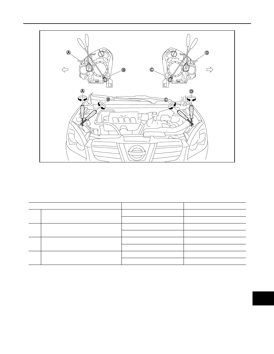
JPLIA0250ZZ
A.
Headlamp RH (UP/DOWN) adjust-
ment screw
B.
Headlamp RH (INSIDE/OUTSIDE)
adjustment screw
C.
Headlamp LH (INSIDE/OUTSIDE)
adjustment screw
D.
Headlamp LH (UP/DOWN) adjust-
ment screw
: Vehicle center
Adjustment screw
Screw driver rotation
Facing direction
A
Headlamp RH (UP/DOWN)
Clockwise
UP
Counterclockwise
DOWN
B
Headlamp RH (INSIDE/OUTSIDE)
Clockwise
INSIDE
Counterclockwise
OUTSIDE
C
Headlamp LH (INSIDE/OUTSIDE)
Clockwise
INSIDE
Counterclockwise
OUTSIDE
D
Headlamp LH (UP/DOWN)
Clockwise
UP
Counterclockwise
DOWN
MA-54
< ON-VEHICLE MAINTENANCE >
CHASSIS MAINTENANCE
CAUTION:
Never cover lens surface with tape, etc. because it is made from plastic.
4.
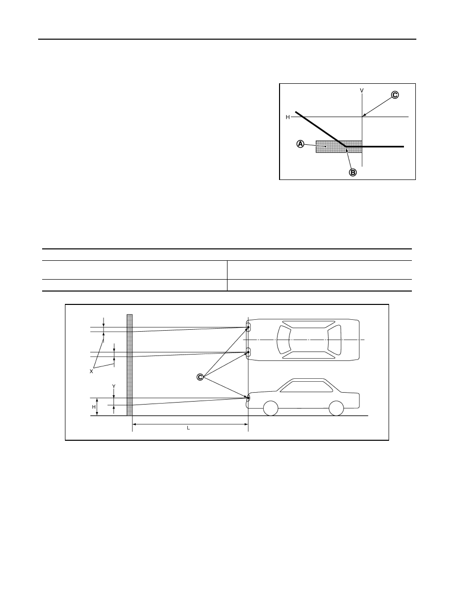
Use the aiming adjustment screw to adjust the elbow point projected by the low beams on the screen, so
that it is within the aiming adjustment area.
Low beam distribution on the screen
Unit: mm (in)
EXHAUST SYSTEM
EXHAUST SYSTEM : Inspection
INFOID:0000000001088650
JSLIA0028ZZ
A.
Aiming adjustment area
B.
Elbow point
C.
Headlamp center
H.
Horizontal center line of headlamp
V.
Vertical center line of headlamp
Aiming adjustment area
Vertical direction (Y)
(Lower side from headlamp center height)
Lateral direction (X)
(Left side from headlamp centerline)
100 – 124 (3.94 – 4.88)
Within 120 (4.72)
C.
Vertical center line of headlamp H.
Horizontal center line of headlamp
L.
Distance from headlamp center to screen
X.
Aiming adjustment area
(lateral)
Y.
Aiming adjustment area
(Vertical)
Distance from headlamp center to screen (L)
: 10 m (32.8 ft)
JSLIA0029ZZ
Нет комментариевНе стесняйтесь поделиться с нами вашим ценным мнением.
Текст