Subaru Impreza 3 / Impreza WRX / Impreza WRX STI. Service manual — part 461
CL-19
Operating Cylinder
CLUTCH SYSTEM
5. Operating Cylinder
A: REMOVAL
1) Remove the intercooler. <Ref. to IN(STI)-12,
REMOVAL, Intercooler.> <Ref. to IN(w/o STI)-12,
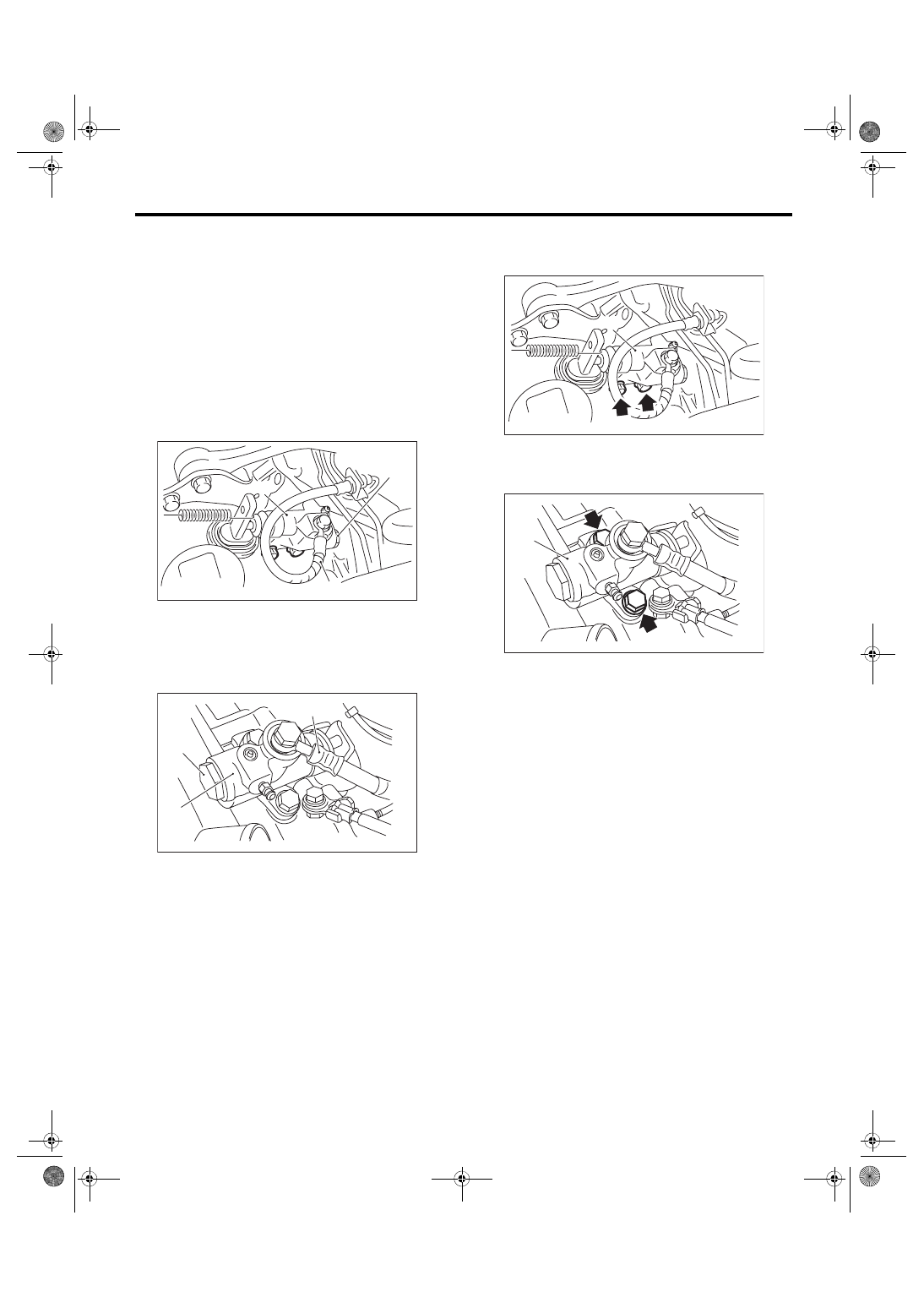
2) Disconnect the clutch hose from the operating
cylinder.
CAUTION:
• Cover the hose joint to prevent the clutch flu-
id from flowing out.
• Do not loosen or remove the cap bolts.
• STI model
• Except for STI model
3) Remove the operating cylinder from the trans-
mission.
• STI model
• Except for STI model
(A) Clutch hose
(B) Operating cylinder
(C) Cap bolt
(A) Clutch hose
(B) Operating cylinder
(C) Cap bolt
CL-00420
(B)
(A)
(C)
CL-00796
(A)
(B)
(C)
(A) Operating cylinder
(A) Operating cylinder
(A)
CL-00419
CL-00823
(A)
CL-20
Operating Cylinder
CLUTCH SYSTEM
B: INSTALLATION
1) Install in the reverse order of removal.
NOTE:
• Use a new gasket.
• Before installing the operating cylinder, apply
grease to the contact point of the release lever and
operating cylinder.
Grease
NICHIMOLY N-130 or equivalent
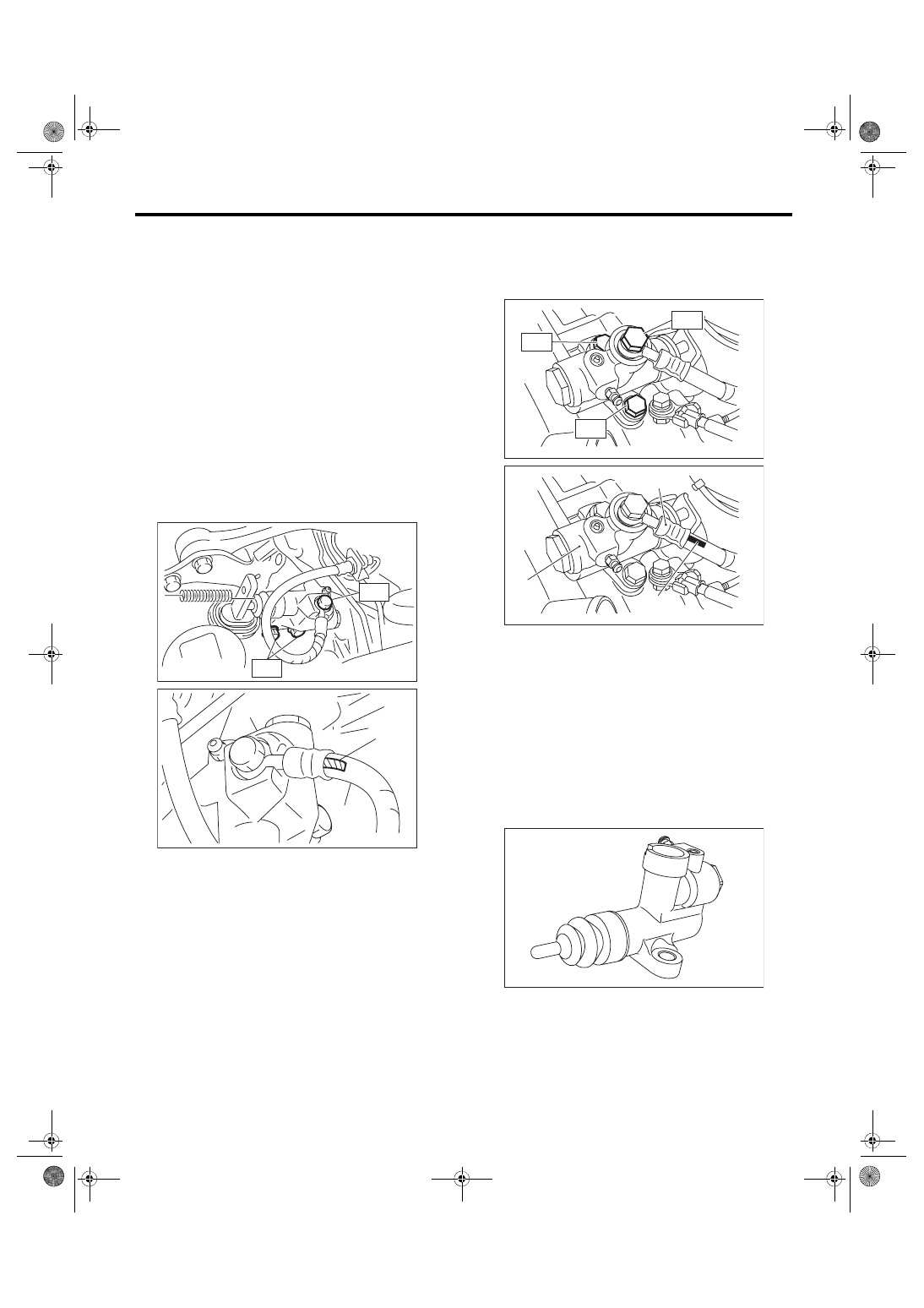
• Be sure to install the clutch hose with the mark
side facing upward.
• Be careful not to twist the clutch hose during in-
stallation.
• STI model
Tightening torque:
T1: 18 N·m (1.8 kgf-m, 13.3 ft-lb)
T2: 41 N·m (4.2 kgf-m, 30.2 ft-lb)
• Except for STI model
Tightening torque:
T1: 18 N·m (1.8 kgf-m, 13.3 ft-lb)
T2: 37 N·m (3.8 kgf-m, 27.3 ft-lb)
2) After bleeding air from the operating cylinder,
ensure that the clutch operates properly.
<Ref. to CL-26, Clutch Fluid Air Bleeding.>
C: DISASSEMBLY
CAUTION:
Do not disassemble the STI model.
1) Remove the boot and push rod.
2) Apply compressed air through clutch hose at-
tachment hole.
NOTE:
Face the piston hole down and place a piece of
wood underneath to prevent the piston from pop-
ping out.
(A) Mark
(B) Clutch hose
(C) Operating cylinder
T2
T1
CL-00421
CL-00802
(A)
(B)
(C)
(A) Clutch hose
(B) Operating cylinder
(C) Mark
CL-00709
T1
T2
T2
CL-00743
(A)
(B)
(C)
CL-00716
CL-21
Operating Cylinder
CLUTCH SYSTEM
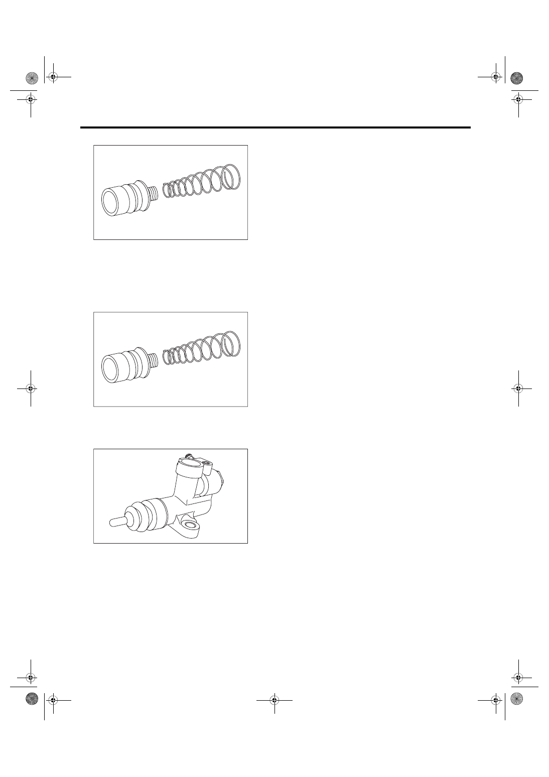
3) Separate the piston and piston spring.
D: ASSEMBLY
NOTE:
During assembly, apply hydraulic oil to all parts.
Recommended clutch fluid:
New FMVSS No. 116 DOT3 or DOT4
1) Install the piston spring onto the piston.
2) Insert piston into the operating cylinder.
3) Install push rod to the boot.
4) Install boot and push rod to the operating cylin-
der.
E: INSPECTION
1) Check that the operating cylinder is not dam-
aged. If operating cylinder is damaged, replace it.
2) Check the operating cylinder for fluid leakage or
damage on the boot. Replace the operating cylin-
der if leaks or damages are noted.
CL-00717
CL-00717
CL-00716
CL-22
Master Cylinder
CLUTCH SYSTEM
6. Master Cylinder
A: REMOVAL
1) Disconnect the ground cable from battery.
2) Thoroughly drain the clutch fluid from the reser-
voir tank.
3) Remove the instrument panel lower cover. <Ref.
to EI-49, REMOVAL, Instrument Panel Lower Cov-
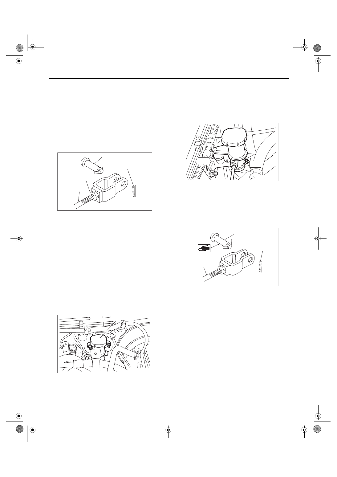
4) Remove the snap pin and clevis pin, and then
separate the push rod of the master cylinder from
clutch pedal.
5) Remove the intercooler. <Ref. to IN(STI)-12,
REMOVAL, Intercooler.> <Ref. to IN(w/o STI)-12,
6) Remove the clutch pipe from the master cylin-
der.
7) Remove the master cylinder and reservoir tank
as a unit.
CAUTION:
Be careful not to spill the brake fluid. Brake flu-
id spilled on the vehicle body will harm the
paint surface; wash it off with water and wipe
clean quickly if spilled.
B: INSTALLATION
1) Install the master cylinder to the vehicle body,
and connect the clutch pipe to the master cylinder.
Tightening torque:
T1: 15 N·m (1.5 kgf-m, 11.1 ft-lb)
T2: 18 N·m (1.8 kgf-m, 13.3 ft-lb)
2) Connect the push rod of the master cylinder to
the clutch pedal, and install the clevis pin and snap
pin.
CAUTION:
Always use a new clevis pin.
NOTE:
Apply grease to the clevis pin.
3) Refill the reservoir tank with recommended
clutch fluid.
4) After bleeding air from the clutch system, ensure
that the clutch operates properly.
<Ref. to CL-26, Clutch Fluid Air Bleeding.>
5) Install the intercooler. <Ref. to IN(STI)-13, IN-
STALLATION, Intercooler.> <Ref. to IN(w/o STI)-
12, INSTALLATION, Intercooler.>
6) Connect the battery ground terminal.
(A) Clevis pin
(B) Snap pin
(C) Push rod
(D) Lock nut
(A) Master cylinder
(B) Clutch pipe
CL-00042
(A)
(B)
(C)
(D)
CL-00152
(A)
(B)
(A) Clevis pin
(B) Snap pin
(C) Push rod
CL-00561
T1
T2
CL-00045
(A)
(B)
(C)
Нет комментариевНе стесняйтесь поделиться с нами вашим ценным мнением.
Текст