Subaru Impreza 3 / Impreza WRX / Impreza WRX STI. Service manual — part 462
CL-23
Master Cylinder
CLUTCH SYSTEM
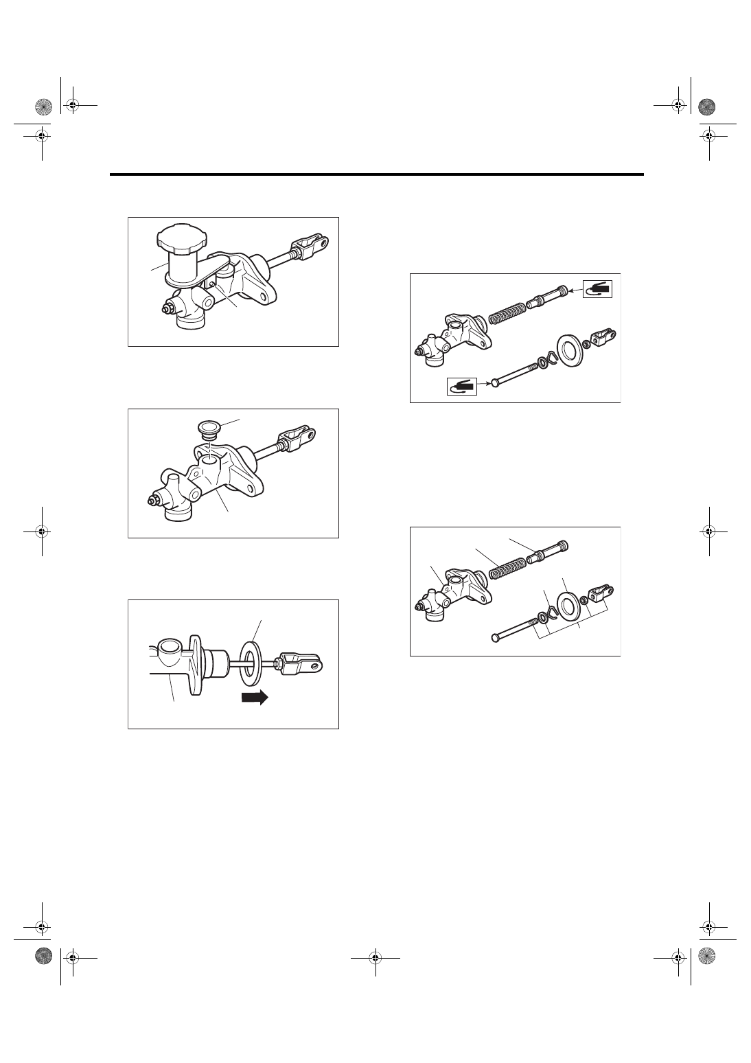
C: DISASSEMBLY
1) Remove the straight pin and reservoir tank.
2) Remove the oil seal.
3) Move the seat towards the rear.
4) Remove the piston stop ring.
CAUTION:
When removing the piston stop ring, be careful
to prevent the rod, washer, piston and return
spring from popping out.
D: ASSEMBLY
1) Apply a coat of grease to the contact surfaces of
the push rod and piston before installation.
Grease:
SILICONE GREASE G-40M (Part No.
004404003) or equivalent
2) Assemble in the reverse order of disassembly.
Tightening torque:
10 N·m (1.0 kgf-m, 7.4 ft-lb)
E: INSPECTION
If any damage, deformation, wear, swelling, rust or
other faults are found on the cylinder, piston, push
rod, reservoir tank, return spring, breather screw,
seat or hose, replace the faulty part.
(A) Reservoir tank
(B) Straight pin
(A) Oil seal
(B) Master cylinder
(A) Seat
(B) Master cylinder
CL-00631
(A)
(B)
CL-00632
(A)
(B)
CL-00513
(A)
(B)
(A) Master cylinder body
(B) Return spring
(C) Piston
(D) Piston stop ring
(E) Push rod ASSY
(F) Seat
CL-00633
CL-00634
(B)
(C)
(D)
(E)
(A)
(F)
CL-24
Clutch Pipe and Hose
CLUTCH SYSTEM
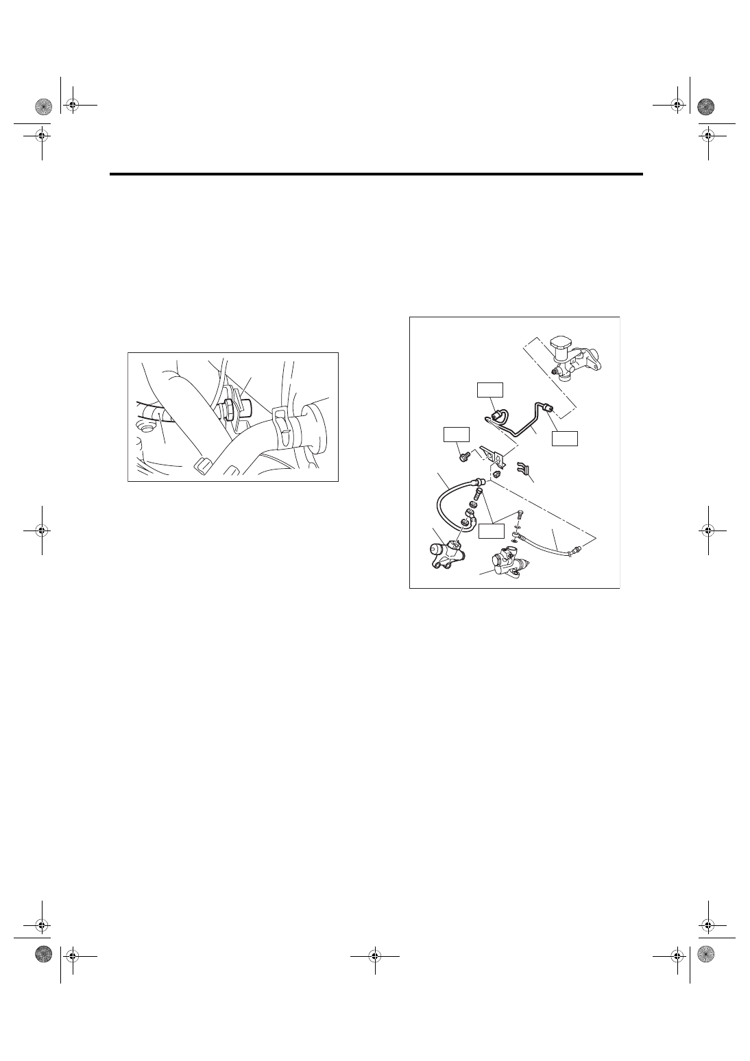
7. Clutch Pipe and Hose
A: REMOVAL
1) Disconnect the ground cable from battery.
2) Remove the intercooler. <Ref. to IN(STI)-12,
REMOVAL, Intercooler.> <Ref. to IN(w/o STI)-12,
3) Drain the clutch fluid. <Ref. to CL-25, Clutch Flu-
4) Disconnect the clutch pipe from the clutch hose
and master cylinder.
5) Remove the clip, then remove the clutch hose
from the bracket.
6) Disconnect the hose from operating cylinder.
7) Remove the clutch bracket.
B: INSTALLATION
Install in the reverse order of removal.
NOTE:
Bleed air from the clutch fluid. <Ref. to CL-26,
Clutch Fluid Air Bleeding.>
Tightening torque:
T1: 15 N·m (1.5 kgf-m, 11.1 ft-lb)
T2: 18 N·m (1.8 kgf-m, 13.3 ft-lb)
T3: 25 N·m (2.5 kgf-m, 18.4 ft-lb)
C: INSPECTION
Check the pipes and hoses for breaks and dam-
age. Check joints for fluid leakage. If crack, break-
age or damage is found, repair or replace the faulty
pipe or hose.
(A) Clip
(B) Clutch hose
CL-00057
(A)
(B)
(A) Clutch pipe
(B) Clip
(C) Clutch hose
(D) STI model
(E) Except for STI model
CL-00804
(B)
(D)
(E)
(C)
(A)
T1
T1
T3
T2
(C)
CL-25
Clutch Fluid
CLUTCH SYSTEM
8. Clutch Fluid
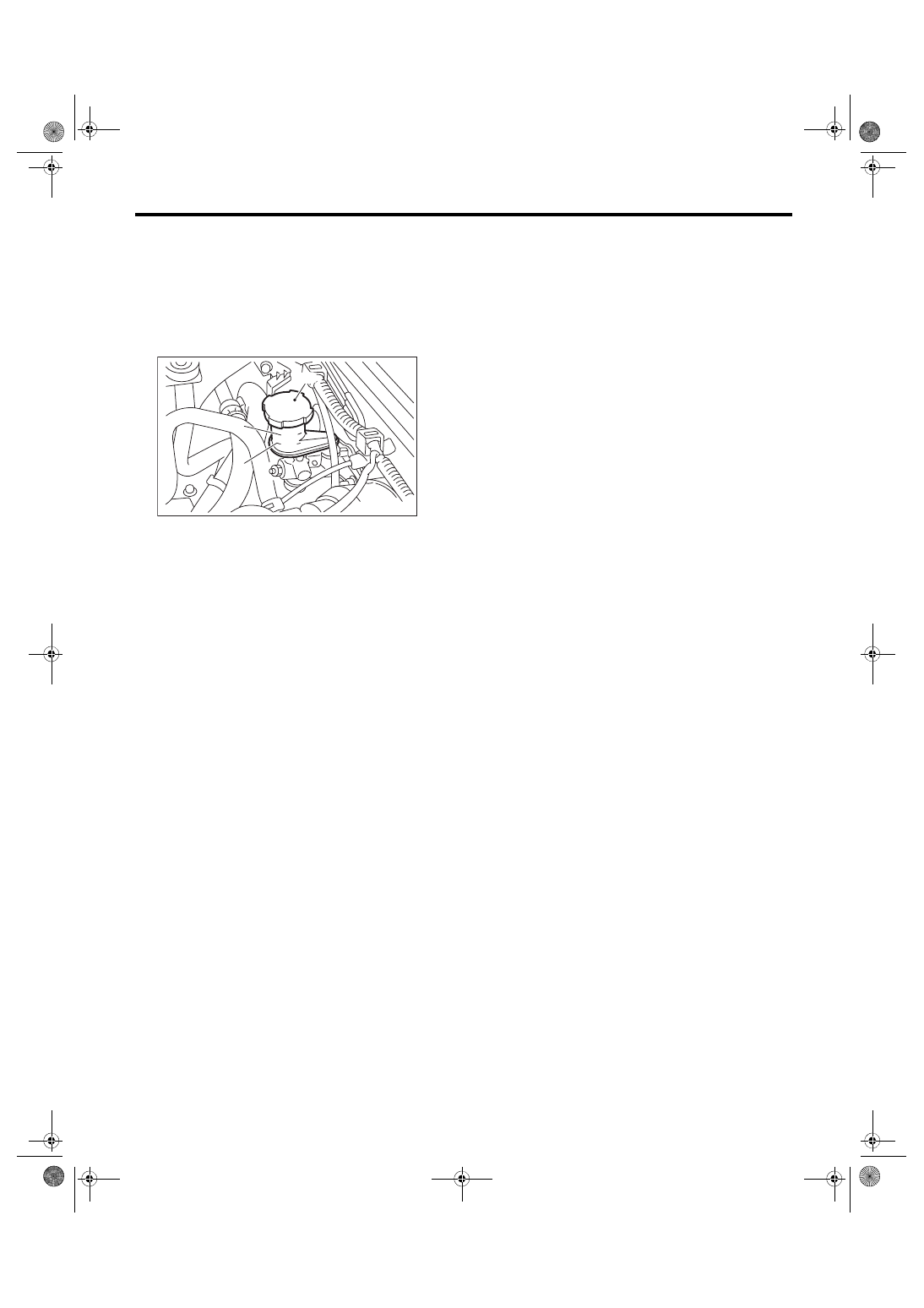
A: INSPECTION
1) Park the vehicle on a level surface.
2) Inspect the fluid level using the scale on the out-
side of the reservoir tank. If the level is below “MIN”,
add fluid to bring it up to “MAX”, and also inspect for
leakage.
B: REPLACEMENT
CAUTION:
• Use new FMVSS No. 116 DOT3 or DOT4.
• Cover the breather with cloth to prevent
brake fluid from being splashed on surround-
ing parts when loosening the breather.
• Avoid mixing brake fluid of different brands
to prevent fluid performance from degrading.
• Be careful not to allow dirt or dust to enter the
reservoir tank.
NOTE:
• During bleeding operation, keep the clutch reser-
voir tank filled with brake fluid to prevent entry of
air.
• Clutch pedal must be operated very slowly.
• Bleed air from the oil line with help of a co-work-
er.
• The required amount of brake fluid is approxi-
mately 70 mL (2.4 US fl oz, 2.5 Imp fl oz) for total
clutch system.
1) Remove the intercooler. <Ref. to IN(STI)-12,
REMOVAL, Intercooler.> <Ref. to IN(w/o STI)-12,
2) Drain the brake fluid from the reservoir tank.
3) Refill the reservoir tank with recommended
brake fluid.
Recommended brake fluid:
New FMVSS No. 116 DOT3 or DOT4
4) If necessary, bleed air from the clutch fluid. <Ref.
to CL-26, Clutch Fluid Air Bleeding.>
5) Install the intercooler. <Ref. to IN(STI)-13, IN-
STALLATION, Intercooler.> <Ref. to IN(w/o STI)-
12, INSTALLATION, Intercooler.>
(A) Reservoir tank
(B) MIN. level
(C) MAX. level
MIN
MAX
( A )
( C )
( B )
CL-00567
CL-26
Clutch Fluid Air Bleeding
CLUTCH SYSTEM
9. Clutch Fluid Air Bleeding
A: PROCEDURE
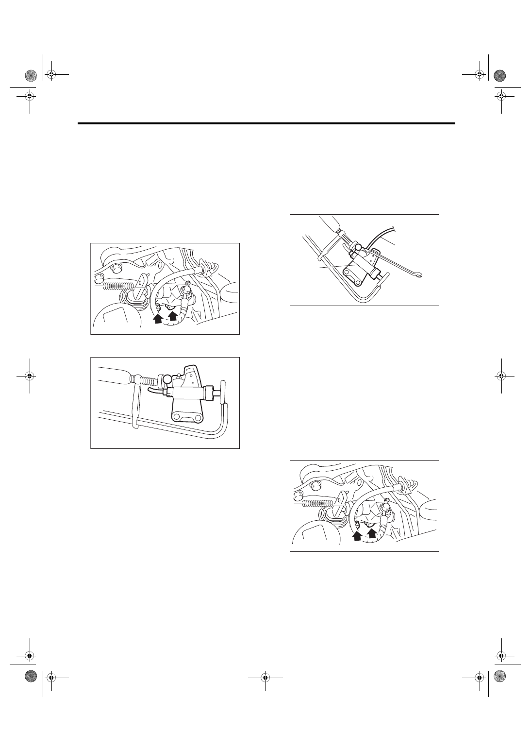
1. STI MODEL
NOTE:
Bleed air from the oil line with help of a co-worker.
1) Remove the intercooler. <Ref. to IN(STI)-12,
2) Remove the operating cylinder.
NOTE:
Do not remove the clutch hose.
3) Hold the piston with a clamp to prevent piston
from popping out.
4) Fit one end of a vinyl tube into the air breather of
the operating cylinder, and put the other end into a
clutch fluid container.
5) Slowly depress the clutch pedal and keep it de-
pressed. Open the air breather to discharge air to-
gether with the clutch fluid. Release the air breather
for 1 or 2 seconds. Next, close the air breather, and
slowly release the clutch pedal.
NOTE:
When performing this procedure, place the screw
portion of the air breather higher than the end of op-
erating cylinder.
6) Repeat procedure 5), until there are no more air
bubbles appearing from the air breather.
CAUTION:
Cover the air breather with cloth to prevent
clutch fluid from being splashed on surround-
ing parts when loosening the breather.
7) Tighten the air breather.
Tightening torque:
7.8 N·m (0.8 kgf-m, 5.8 ft-lb)
8) Install the operating cylinder.
Tightening torque:
41 N·m (4.2 kgf-m, 30.2 ft-lb)
9) After stepping on the clutch pedal, make sure
that there are no leaks evident in the entire clutch
system.
10) After bleeding the air from clutch system, en-
sure that the clutch operates properly.
11) Install the intercooler. <Ref. to IN(STI)-13, IN-
CL-00422
CL-00247
(A) Operating cylinder
(B) Vinyl tube
(A)
CL-00248
(B)
CL-00422
Нет комментариевНе стесняйтесь поделиться с нами вашим ценным мнением.
Текст