Subaru Impreza 3 / Impreza WRX / Impreza WRX STI. Service manual — part 459
CL-11
Clutch Disc and Cover
CLUTCH SYSTEM
2. Clutch Disc and Cover
A: REMOVAL
1) Remove the transmission assembly from the ve-
hicle. <Ref. to 6MT-31, REMOVAL, Manual Trans-
mission Assembly.> <Ref. to 5MT-23, REMOVAL,
Manual Transmission Assembly.>
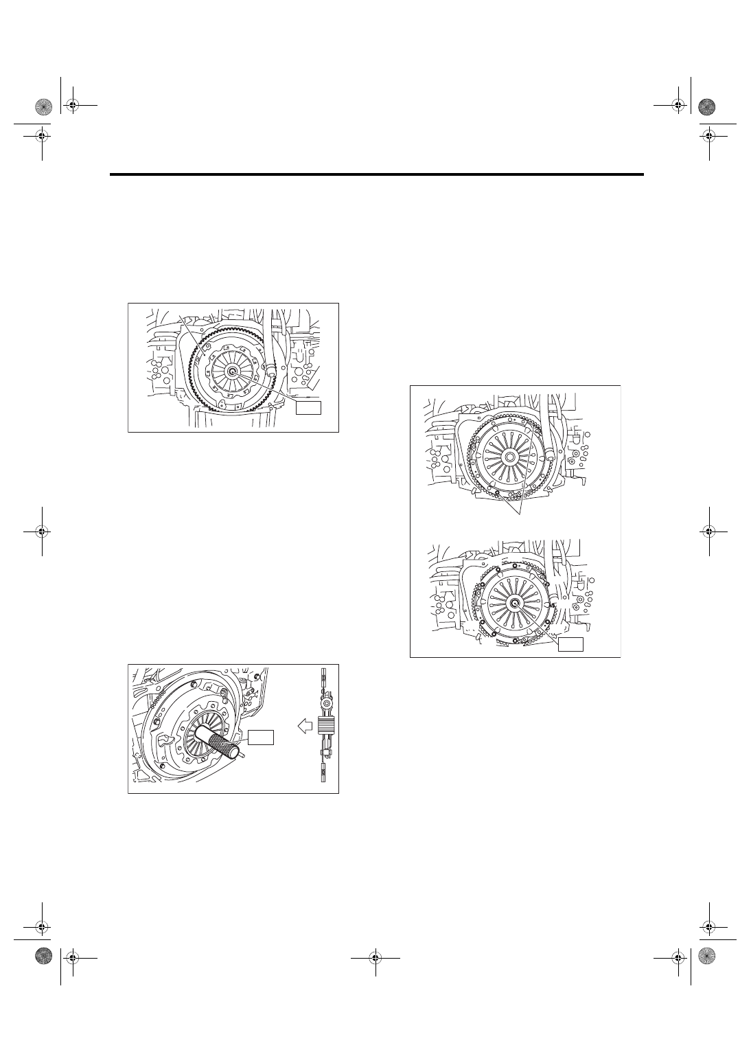
2) Attach the ST on the flywheel.
ST 499747100
CLUTCH DISC GUIDE
3) Remove the clutch cover and clutch disc.
NOTE:
• Take care not to allow oil to touch the clutch disc
face.
• Do not disassemble the clutch cover or clutch
disc.
B: INSTALLATION
1) Insert the ST into the clutch disc and attach to
the flywheel by inserting the ST end into pilot bear-
ing.
NOTE:
When installing the clutch disc, be careful to attach
in the correct direction.
ST 499747100
CLUTCH DISC GUIDE
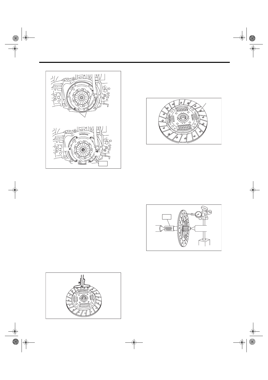
2) Install the clutch cover to the flywheel and tight-
en the bolts to the specified torque.
NOTE:
• When installing a clutch cover to the flywheel,
position the clutch cover so that the spacing be-
tween the unbalance marks (paint mark) on the fly-
wheel and clutch cover is 120° or more apart. (The
unbalance mark indicates the direction of residual
unbalance.)
• Temporarily tighten the bolts by hand. Each bolt
should be tightened to the specified torque in a
crisscross order.
Tightening torque:
16 N·m (1.6 kgf-m, 11.8 ft-lb)
• STI model
(A) Clutch cover
(A) Flywheel side
CL-00011
( A )
S T
CL-00208
(A)
ST
(A) Unbalance mark (paint)
CL-00792
( A )
S T
( 2 )
( 5 )
( 3 ) ( 1 )
( 6 )
( 4 )
( 7 )
( 8 )
( 9 )
CL-12
Clutch Disc and Cover
CLUTCH SYSTEM
• Except for STI model
3) Remove the ST.
ST 499747100
CLUTCH DISC GUIDE
4) Install the transmission assembly. <Ref. to 6MT-
33, INSTALLATION, Manual Transmission Assem-
bly.> <Ref. to 5MT-26, INSTALLATION, Manual
C: INSPECTION
1. CLUTCH DISC
1) Facing wear
Measure the depth from the facing surface to the
rivet head. Replace if the face is worn locally or
worn down to less than the specified value.
Depth to rivet head:
Limit of sinking
0.8 mm (0.031 in)
NOTE:
Do not wash the clutch disc with any type of clean-
ing fluid.
2) Hardened facing
Replace the clutch disc.
3) Oil soakage on facing
Replace the clutch disc and inspect the transmis-
sion front oil seal, transmission case mating sur-
face, engine rear oil seal and other locations for oil
leakage.
4) Deflection on facing
If deflection exceeds the specified value at the out-
er circumference of the facing, replace the clutch
disc.
ST 499747100
CLUTCH DISC GUIDE
Limit for deflection:
STI model
0.7 mm (0.028 in) at R = 115 mm (4.53 in)
Except for STI model
0.7 mm (0.028 in) at R = 110 mm (4.33 in)
(A) Unbalance mark (paint)
CL-00013
( A )
S T
( 2 )
( 5 )
( 3 )
( 1 )
( 6 )
( 4 )
CL-00014
(A) Clutch facing
CL-00015
(A)
CL-00016
S T
CL-13
Clutch Disc and Cover
CLUTCH SYSTEM
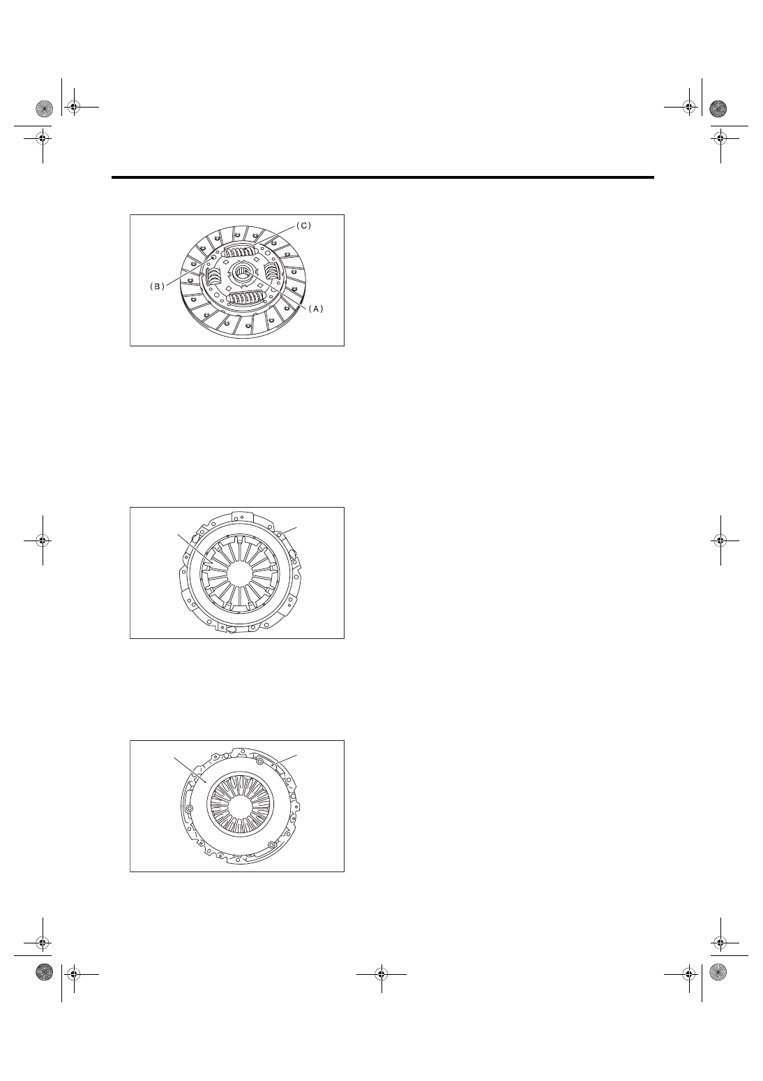
5) If there is spline wear, loose rivets, failed damper
springs, etc., replace the clutch disc.
2. CLUTCH COVER
NOTE:
Visually check the following items without disas-
sembling, and replace or repair if defective.
1) Loose thrust rivet
2) Damaged or worn bearing contact area at the
center of diaphragm spring
3) Damaged or worn disc contact surface of the
pressure plate
4) Loose strap plate installation area
5) Worn diaphragm sliding area
(A) Spline
(B) Rivet
(C) Damper spring
(A) Thrust rivet
(B) Diaphragm spring
(A) Pressure plate
(B) Strap plate
CL-00017
CL-00018
( A )
( B )
CL-00176
(A)
(B)
CL-14
Flywheel
CLUTCH SYSTEM
3. Flywheel
A: REMOVAL
1) Remove the transmission assembly. <Ref. to
6MT-31, REMOVAL, Manual Transmission As-
sembly.> <Ref. to 5MT-23, REMOVAL, Manual
2) Remove the clutch cover and clutch disc. <Ref.
to CL-11, REMOVAL, Clutch Disc and Cover.>
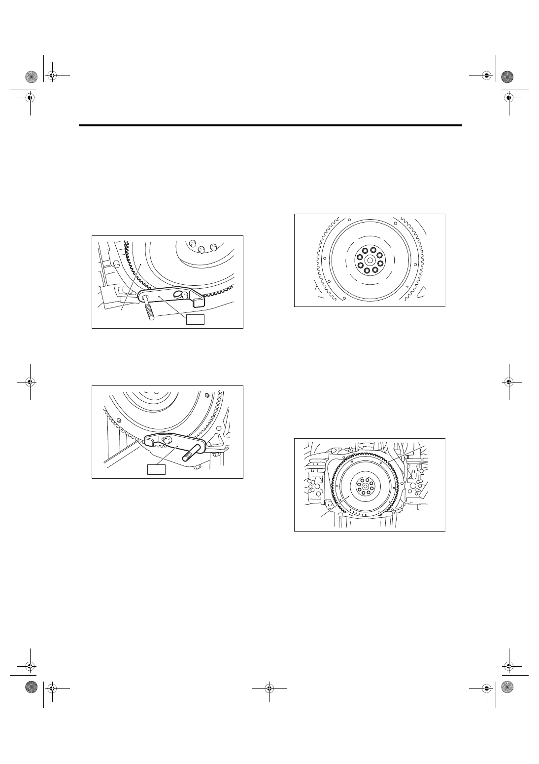
3) Using the ST, remove the flywheel.
ST 498497100
CRANKSHAFT STOPPER
B: INSTALLATION
1) Install the flywheel and ST.
ST 498497100
CRANKSHAFT STOPPER
2) Tighten the flywheel mounting bolts to the spec-
ified torque.
NOTE:
Tighten the flywheel attachment bolts gradually.
Each bolt should be tightened to the specified
torque in crisscross order.
Tightening torque:
75 N·m (7.6 kgf-m, 55.3 ft-lb)
3) Install the clutch disc and cover. <Ref. to CL-11,
INSTALLATION, Clutch Disc and Cover.>
4) Install the transmission assembly. <Ref. to 6MT-
33, INSTALLATION, Manual Transmission Assem-
bly.> <Ref. to 5MT-26, INSTALLATION, Manual
C: INSPECTION
CAUTION:
Because the center bearing is grease-sealed
and is a non-lubrication type, do not wash with
gasoline or solvents.
1) If there is damage or defectiveness in the facing
sliding surface or ring gear, replace the flywheel.
2) Smoothness of rotation
Rotate the ball bearing while applying pressure in
the thrust direction.
3) If noise or excessive play is noted, replace the
flywheel.
(A) Flywheel
CL-00019
S T
( A )
CL-00801
S T
(A) Flywheel
(B) Ring gear
CL-00021
( 1 )
( 2 )
( 3 )
( 4 )
( 5 )
( 6 )
( 7 )
( 8 )
CL-00022
( B )
( A )
Нет комментариевНе стесняйтесь поделиться с нами вашим ценным мнением.
Текст