Subaru Impreza 3 / Impreza WRX / Impreza WRX STI. Service manual — part 602
AC(diag)-13
Diagnostics for A/C System Malfunction
HVAC SYSTEM (AUTO A/C) (DIAGNOSTICS)
6. Diagnostics for A/C System Malfunction
A: A/C OR SELF-DIAGNOSIS SYSTEMS DO NOT OPERATE
TROUBLE SYMPTOM:
• Set temperature is not indicated on the display, switch LEDs are faulty and switches do not operate.
• Self-diagnosis system does not operate.
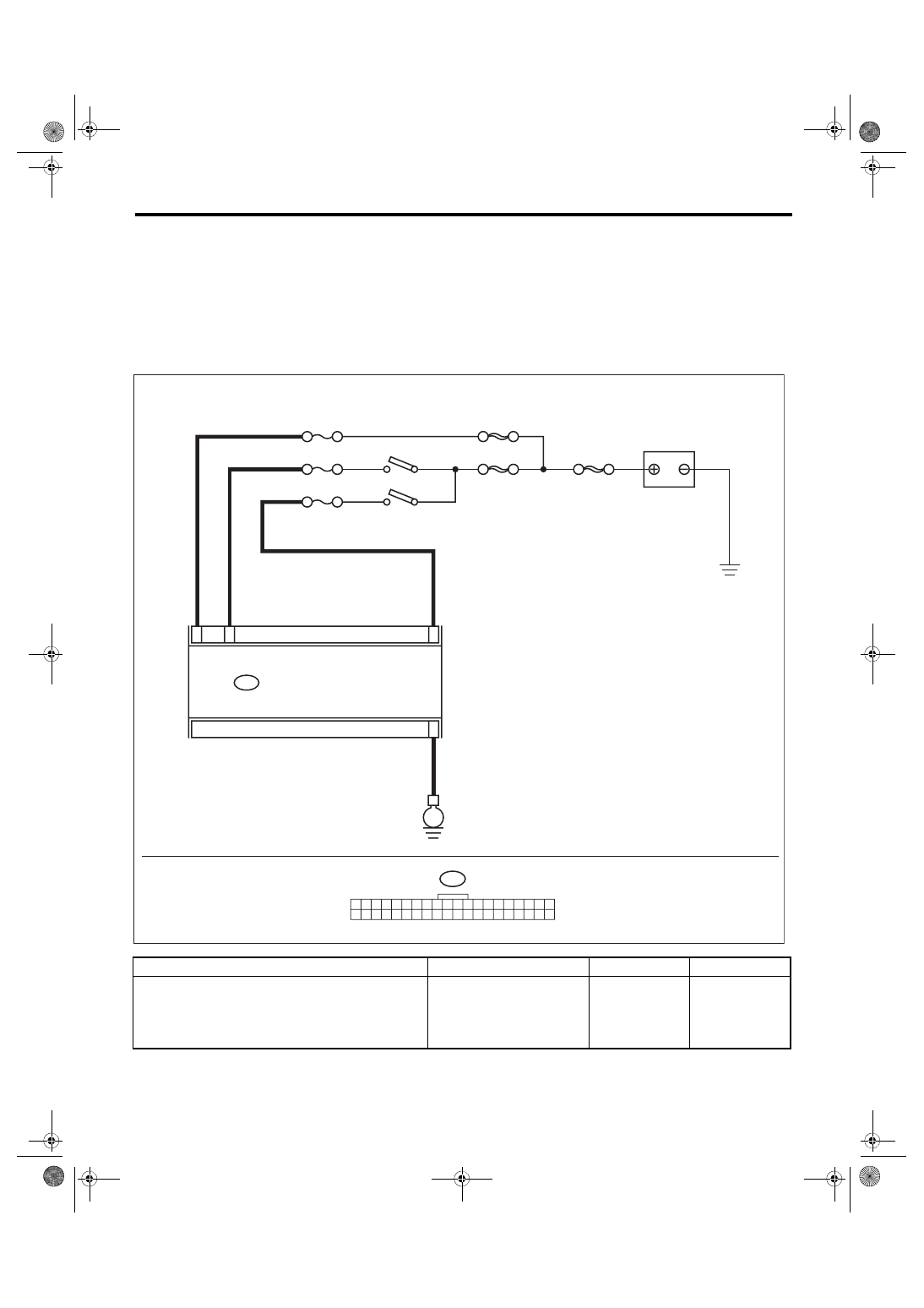
WIRING DIAGRAM:
Air conditioning system, auto A/C model <Ref. to WI-77, AUTO A/C MODEL, WIRING DIAGRAM, Air Con-
Step
Check
Yes
No
1
CHECK FUSE.
1) Turn the ignition switch to OFF.
2) Remove the fuse No. 7, No. 22 and No. 31
from fuse & relay box.
3) Check the condition of fuse.
Is the fuse blown out?
Replace the fuse. Go to step
i88
1 2 3 4 5 6 7 8 9 10 11 12 13 14 15 16 17 18 19 20
21 22 23 24 25 26 27 28 29 30 31 32 33 34 35 36 37 38 39 40
i88
31
15
34
32
SBF-8
E
SBF-6
AC-02426
ACC
MAIN SBF
F/B No. 7
F/B No. 22
F/B No. 31
IGNITION SWITCH
BATTERY
AUTO A/C CONTROL MODULE

AC(diag)-14
Diagnostics for A/C System Malfunction
HVAC SYSTEM (AUTO A/C) (DIAGNOSTICS)
2
CHECK A/C CONTROL MODULE POWER
CIRCUIT.
1) Remove the A/C control module.
2) Disconnect the A/C control module harness
connector.
3) Turn the ignition switch to ACC, and mea-
sure the voltage between A/C control module
harness connector terminal and chassis
ground.
Connector & terminal
(i88) No. 15 (+) — Chassis ground (–):
Is the voltage 10 V or more?
Check for open or
short circuit in the
harness between
A/C control module
and fuse.
3
CHECK A/C CONTROL MODULE POWER
CIRCUIT.
Measure the voltage between A/C control mod-
ule harness connector terminal and chassis
ground after turning the ignition switch to ON.
Connector & terminal
(i88) No. 32 (+) — Chassis ground (–):
Is the voltage 10 V or more?
Check for open or
short circuit in the
harness between
A/C control module
and fuse.
4
CHECK A/C CONTROL MODULE GROUND
CIRCUIT.
Measure the resistance of harness between A/C
control module and chassis ground after turning
the ignition switch to OFF.
Connector & terminal
(i88) No. 34 — Chassis ground:
Is the resistance less than 10
Ω?
Repair the harness
for ground line.
5
CHECK FOR POOR CONTACT.
Check poor contact of auto A/C control module
connector.
Is there poor contact of connec-
tor?
Repair the connec-
tor.
Replace the auto
A/C control mod-
ule. <Ref. to AC-
31, REMOVAL,
Control Unit (Auto
A/C Model).>
Step
Check
Yes
No
AC(diag)-15
Diagnostics for A/C System Malfunction
HVAC SYSTEM (AUTO A/C) (DIAGNOSTICS)
B: BLOWER MOTOR DOES NOT ROTATE
TROUBLE SYMPTOM:
• Blower motor does not rotate.
• Blower motor does not change speeds.
WIRING DIAGRAM:
Air conditioning system, auto A/C model <Ref. to WI-77, AUTO A/C MODEL, WIRING DIAGRAM, Air Con-
Step
Check
Yes
No
1
CHECK FUSE.
1) Remove fuse No. 22, 27 and 28 from fuse &
relay box.
2) Check the condition of fuse.
Is any fuse blown out?
Replace the fuse. Go to step
2
CHECK POWER SUPPLY OF BLOWER MO-
TOR RELAY.
1) Turn the ignition switch to OFF.
2) Remove the blower motor relay.
3) Turn the ignition switch to ON.
4) Use a tester to measure the voltage
between the blower motor relay connector and
chassis ground.
Connector & terminal
(B386) No. 2 (+) — Chassis ground (–):
Is the voltage 10 V or more?
Repair the open
circuit of blower
motor power sup-
ply line harness.
3
CHECK BLOWER MOTOR RELAY.
1) Turn the ignition switch to OFF.
2) Connect the battery positive terminal to the
blower motor relay terminal No. 2, and the neg-
ative terminal to No. 3.
3) Using the tester, measure the resistance
between terminals.
Connector & terminal
(Relay) No. 1 — No. 4:
Is the resistance less than 1 Ω? Go to step
Replace the blower
motor relay.
B386
2
1
3
4
23
11
i1
5 6 7 8
2
1
9
4
3
10
24
22
23
25
27
26
28
11 12 13
14 15 16
17 18 19 20 21
4
3
2
1
B57
2
1
B87
12
B57
4
2
3
1
B87
9
i1
B36
B386
1
2
4
3
1 2 3 4 5 6 7 8 9 10 11 12 13 14 15 16 17 18 19 20
21 22 23 24 25 26 27 28 29 30 31 32 33 34 35 36 37 38 39 40
i88
40
i88
AC-02508
AUTO A/C
CONTROL MODULE
TO POWER SUPPLY CIRCUIT
FB-46
F/B FUSE NO. 22
(IG)
FB-8
F/B FUSE NO.27 (B)
F/B FUSE NO.28 (B)
BLOWER MOTOR RELAY
BLOWER
MOTOR
POWER TRANSISTOR
AC(diag)-16
Diagnostics for A/C System Malfunction
HVAC SYSTEM (AUTO A/C) (DIAGNOSTICS)
4
CHECK HARNESS.
1) Remove the auto A/C control module.
2) Measure the resistance between auto A/C
control module and relay using a tester.
Connector & terminal
(B386) No. 3 — (i88) No. 9:
Is the resistance less than 1 Ω? Go to step
Repair or replace
the harness.
5
CHECK BLOWER MOTOR POWER SUPPLY.
1) Install the blower motor relay and auto A/C
control module.
2) Turn the ignition switch to ON.
3) Turn the blower fan switch to ON.
4) Use a tester to measure the voltage
between the blower motor and chassis ground.
Connector & terminal
(B87) No. 2 (+) — Chassis ground (–):
Is the voltage 10 V or more?
Repair or replace
the harness
between relay and
the blower motor.
6
CHECK BLOWER MOTOR.
1) Turn the ignition switch to OFF.
2) Disconnect the connector from blower
motor.
3) Connect the battery positive terminal to the
blower motor connector terminal No. 2, and the
negative terminal to No. 1.
4) Make sure the blower motor runs.
Does the blower motor run?
Replace the blower
motor. <Ref. to AC-
26, REMOVAL,
Blower Motor.>
7
CHECK HARNESS.
1) Disconnect the power transistor connector.
2) Disconnect the auto A/C control module
connector.
3) Using the tester, measure the resistance
between terminals of harness.
Connector & terminal
(B57) No. 1 — Chassis ground:
(B57) No. 2 — (i88) No. 40:
(B57) No. 3 — (B87) No. 1:
(B57) No. 4 — (B87) No. 2:
(B57) No. 4 — (B386) No. 4:
Is the resistance less than 1 Ω? Go to step
Repair or replace
the harness.
8
CHECK FAN CONTROL SIGNAL.
1) Connect the disconnected connectors.
2) Turn the ignition switch to ON.
3) Change the fan dial from 1st to 7th.
4) Measure the voltage between the power
transistor and chassis ground using a tester.
Connector & terminal
(B57) No. 2 (+) — Chassis ground (–):
Is the voltage approx. 10 V at
1st and approx. 1 V at 7th?
Replace the power
transistor. <Ref. to
AC-27, REMOVAL,
Power Transistor
(Auto A/C Model).>
9
CHECK FOR POOR CONTACT.
Check poor contact of auto A/C control module
connector.
Is there poor contact of connec-
tor?
Repair the connec-
tor.
Replace the auto
A/C control mod-
ule. <Ref. to AC-
31, REMOVAL,
Control Unit (Auto
A/C Model).>
Step
Check
Yes
No
Нет комментариевНе стесняйтесь поделиться с нами вашим ценным мнением.
Текст