Subaru Impreza 3 / Impreza WRX / Impreza WRX STI. Service manual — part 600
AC(diag)-5
Electrical Component Location
HVAC SYSTEM (AUTO A/C) (DIAGNOSTICS)
3. Electrical Component Location
A: LOCATION
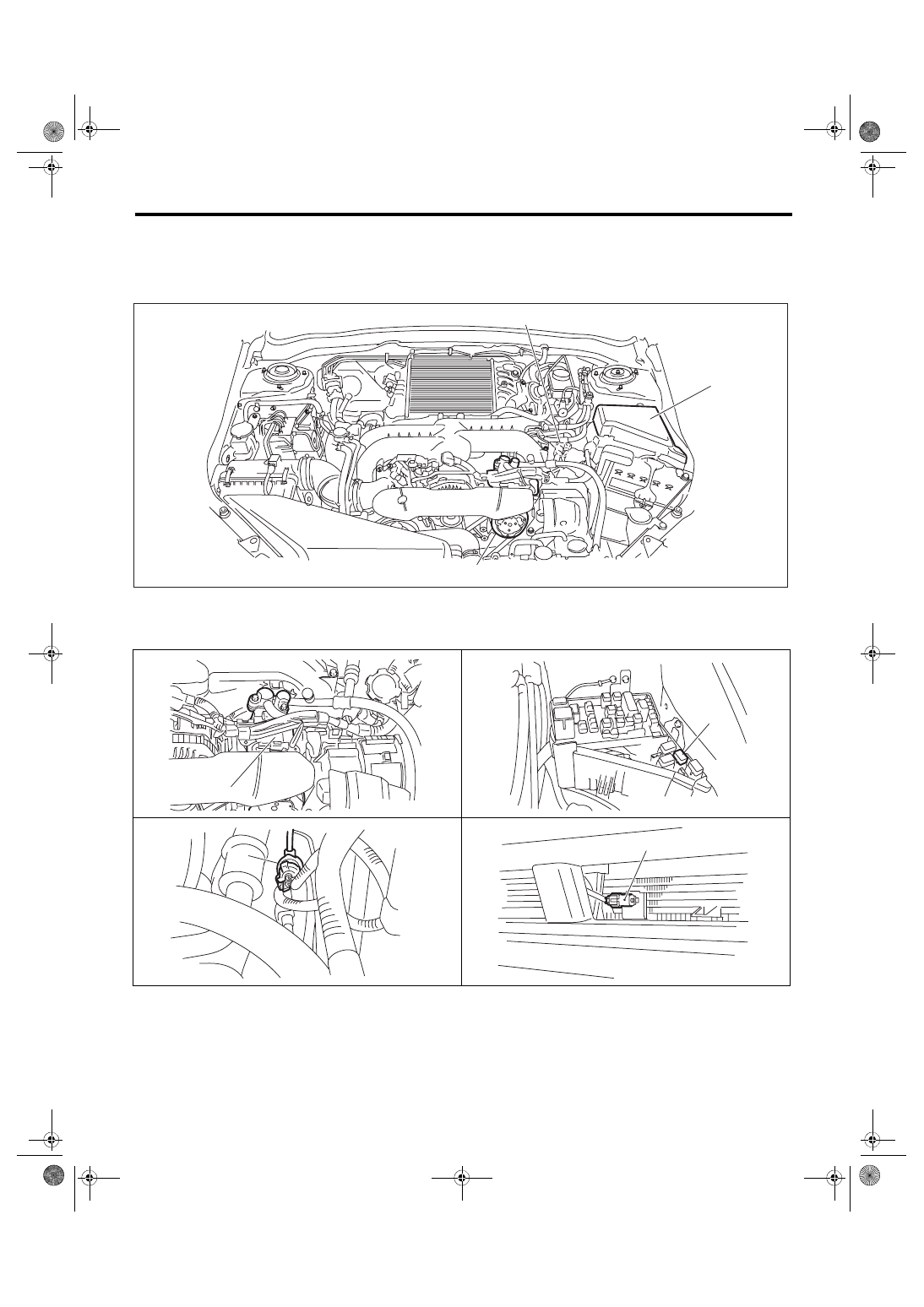
1. ENGINE COMPARTMENT
(1)
A/C compressor
(3)
Pressure switch
(4)
Ambient sensor
(2)
A/C relay
AC-01879
(2)
(1)
(3)
AC-02013
(1)
(2)
AC-01603
AC-00814
(3)
AC-00816
(4)
AC(diag)-6
Electrical Component Location
HVAC SYSTEM (AUTO A/C) (DIAGNOSTICS)
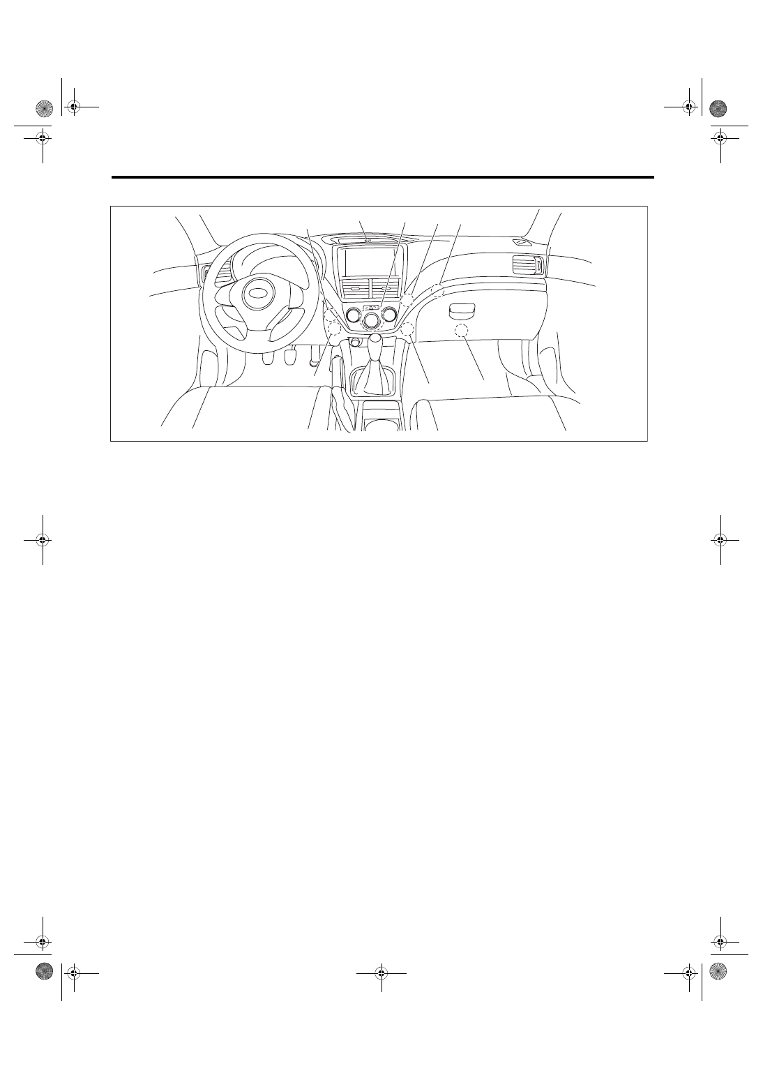
2. COMPARTMENT
(1)
Evaporator sensor
(4)
Blower motor
(7)
Mode door actuator
(2)
Air mix door actuator
(5)
Sunload sensor
(8)
In-vehicle sensor
(3)
Auto A/C control module
(6)
Intake door actuator
AC-01712
(7)
(6)
(4)
(3)
(2)
(1)
(5)
(8)
AC(diag)-7
Auto A/C Control Module I/O Signal
HVAC SYSTEM (AUTO A/C) (DIAGNOSTICS)
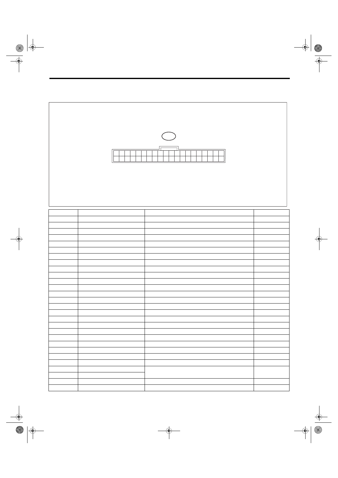
4. Auto A/C Control Module I/O Signal
A: ELECTRICAL SPECIFICATION
Terminal No.
Content
Measuring condition
Specification
1
Mode actuator # 4
Actuator operating
8 V or more
2
Mode actuator # 3
Actuator operating
8 V or more
3
Mode actuator # 2
Actuator operating
8 V or more
4
Mode actuator # 1
Actuator operating
8 V or more
6
Intake door actuator (FRESH)
FRESH mode
1 V or less
7
Intake door actuator (MIX)
MIX mode
1 V or less
8
Intake door actuator (RECIRC)
RECIRC mode
1 V or less
9
Blower fan ON signal
Blower fan is ON
1 V or less
11
A/C cut-off signal
A/C is cut off
1 V or less
14
GND for sensors
Always
1 V or less
15
ACC power supply
ACC ON
Battery voltage
16
Sunload sensor
Sunlight is contacting sensor
1 — 4 V
17
RECIRC sensor
Ignition switch ON
25°C: 2.5 V
18
Post evaporator sensor
Depends on temperature after the evaporator.
1 — 4.5 V
19
CAN Lo
Digital signal; can not be measured
—
20
CAN Hi
Digital signal; can not be measured
—
25
Air mix actuator #4
Air mix actuator is operating
8 V or more
26
Air mix actuator #3
Air mix actuator is operating
8 V or more
27
Air mix actuator #2
Air mix actuator is operating
8 V or more
28
Air mix actuator #1
Air mix actuator is operating
8 V or more
31
BATT
Always
Battery voltage
32
IGN
Ignition ON
Battery voltage
34
Ground
Always
1 V or less
36
A/C ON signal
A/C is operating
8 V or more
35
ILL–
Illumination ON (measure between 37 — 35)
Battery voltage
37
ILL+
39
Rr defogger switch output
When the rear defogger switch is ON
1 V or less
40
Fan control signal
Ignition switch: ON, Blower switch: ON
8 V or more
i88
1
2
3
4
5
6
7
8
9
10
11
12
13
14
15
16
17
18
19
20
21
22
23
24
25
26
27
28
29
30
31
32
33
34
35
36
37
38
39
40
AC-01692
AC(diag)-8
Auto A/C Control Module I/O Signal
HVAC SYSTEM (AUTO A/C) (DIAGNOSTICS)
B: WIRING DIAGRAM
1. AIR CONDITIONER AUTO A/C MODEL
Нет комментариевНе стесняйтесь поделиться с нами вашим ценным мнением.
Текст