Subaru Impreza 3 / Impreza WRX / Impreza WRX STI. Service manual — part 393
CS-23
Reverse Check Cable
CONTROL SYSTEMS
3. Reverse Check Cable
A: REMOVAL
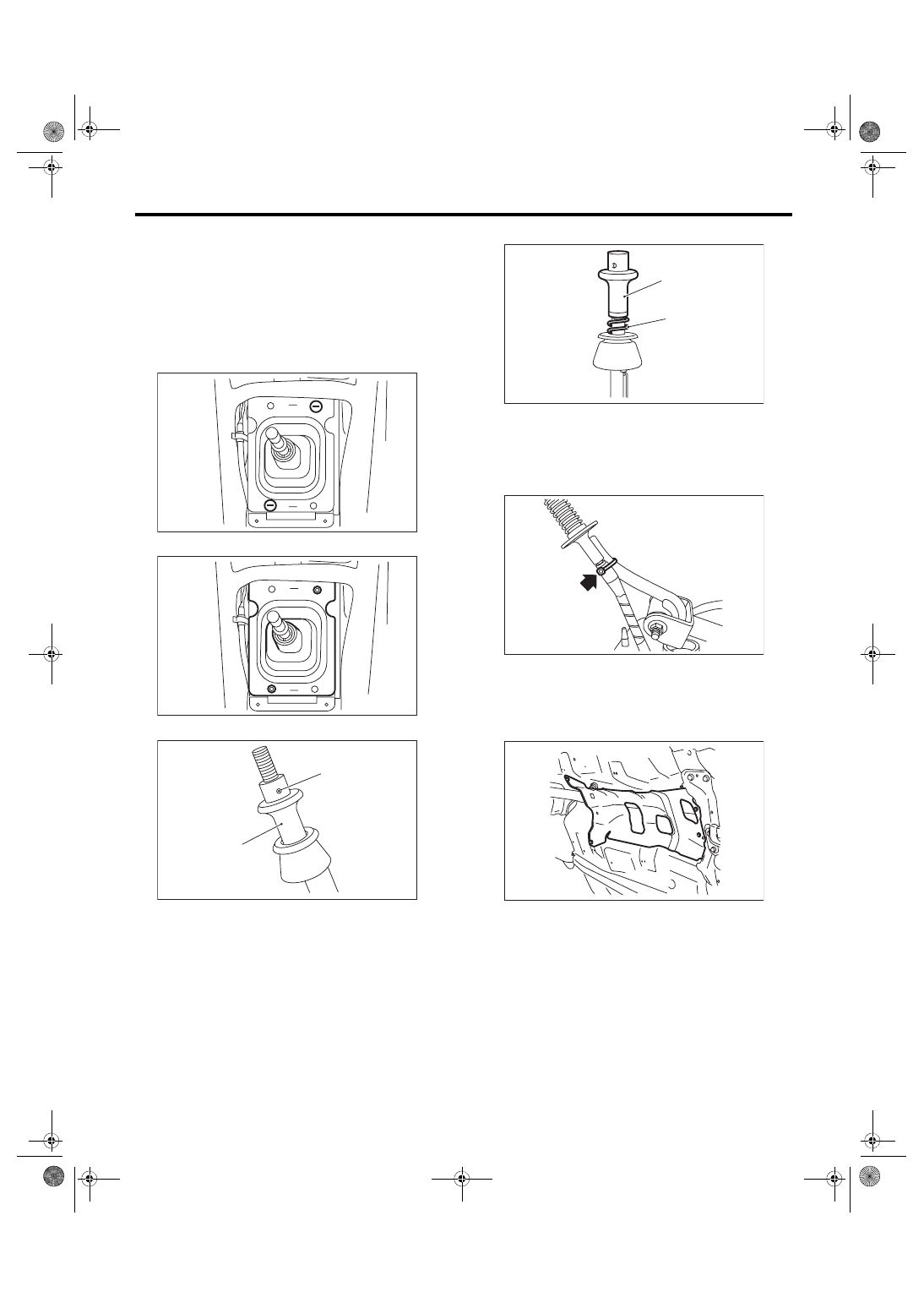
1) Remove the gear shift knob.
2) Remove the console box. <Ref. to EI-51, RE-
3) Remove the console side cover and console
front panel.
4) Remove the clamp.
5) Remove the boot and insulator assembly.
6) Remove the spring pin from the slider.
7) Remove the slider and spring.
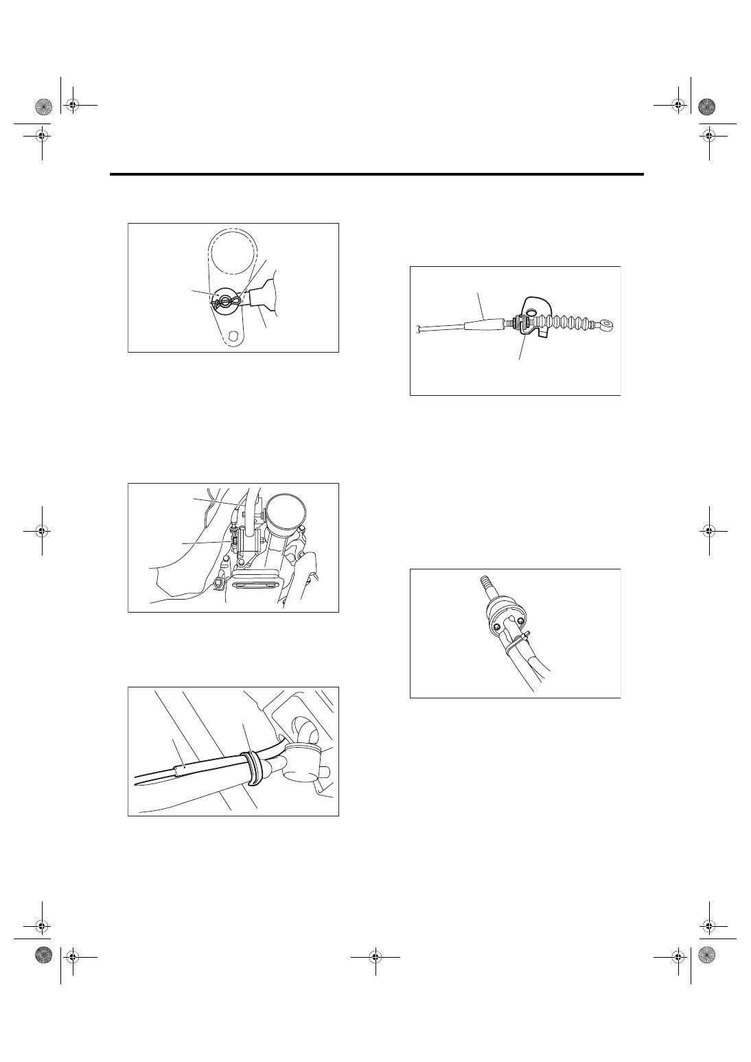
8) Cut the band clip, and separate the reverse
check cable from the gear shift lever.
9) Lift up the vehicle.
10) Remove the under cover.
11) Remove the center exhaust pipe. <Ref. to
EX(STI)-8, REMOVAL, Center Exhaust Pipe.>
12) Remove the heat shield cover.
13) Remove the crossmember. <Ref. to 6MT-29,
REMOVAL, Transmission Mounting System.>
(A) Slider
(B) Spring pin
CS-00926
CS-00927
CS-00225
(A)
(B)
(A) Slider
(B) Spring
CS-00226
(A)
(B)
CS-00227
MT-01660
CS-24
Reverse Check Cable
CONTROL SYSTEMS
14) Remove the snap pin and washer, and sepa-
rate the reverse check cable from the reverse
check lever.
15) Move the transmission to the right side, and re-
move the stay bolts and the reverse check cable.
NOTE:
If the transmission is not moved aside, the stay
bolts may contact the body and cause damage.
16) Lift up the stay clip, and separate the stay from
the reverse check cable.
17) Pull out the reverse check cable from under-
side of the vehicle to remove it.
NOTE:
Be careful not to damage the inner boot.
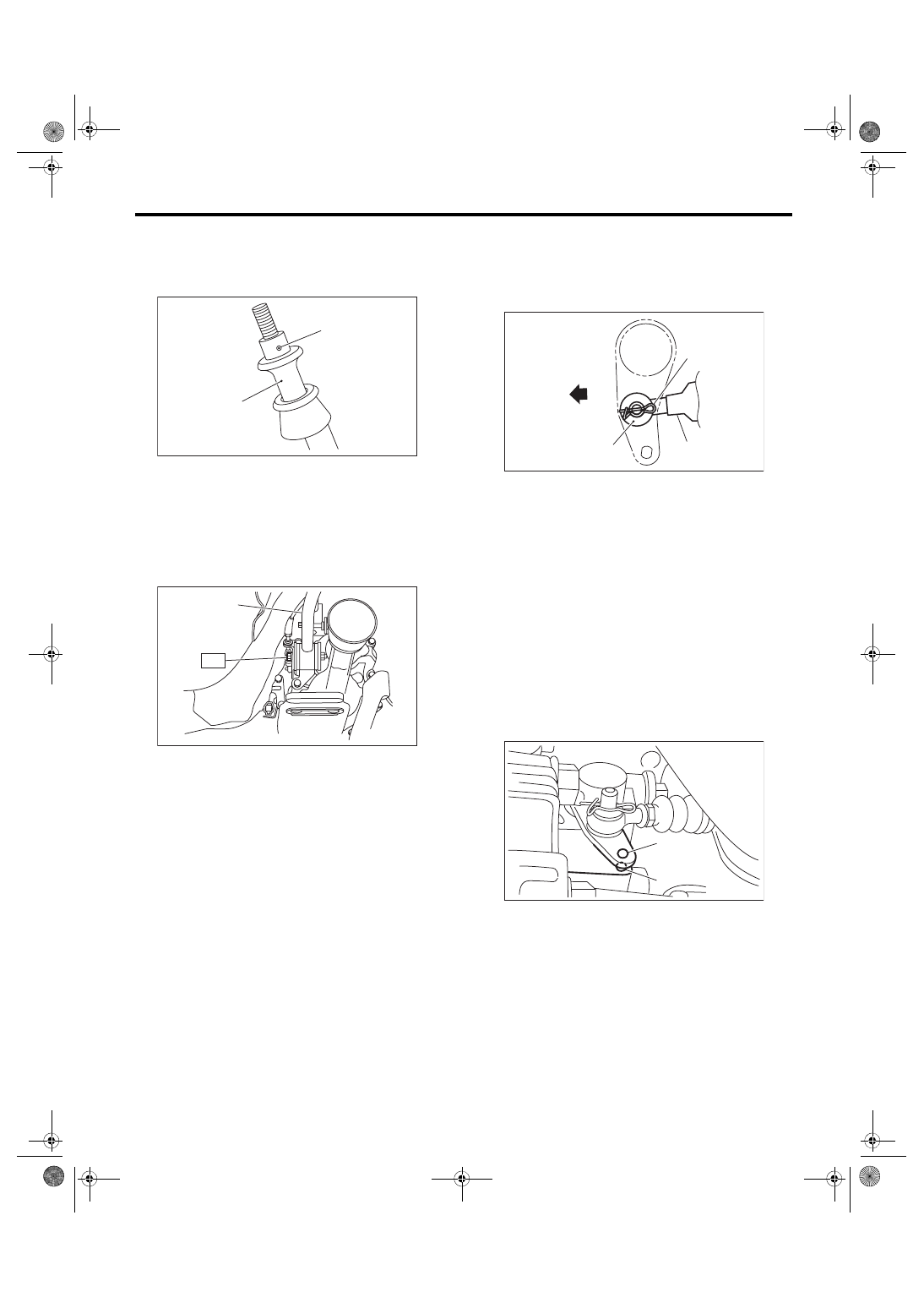
18) Loosen the lock nut, and remove the reverse
check cable from the cable plate.
B: INSTALLATION
1) Insert the reverse check cable into the inner boot
hole from underside of the vehicle.
2) Insert the reverse check cable into the gear shift
lever assembly, and secure it with the band clip.
NOTE:
• Cut the excess band clip.
• Make sure that the reverse check cable is insert-
ed into the gearshift lever with no gaps.
(A) Snap pin
(B) Washer
(C) Reverse check cable
(A) Stay
(B) Stay bolt
(A) Reverse check cable
(B) Clip
CS-00220
(B)
(A)
(C)
CS-00245
(A)
(B)
CS-00243
(A)
(B)
(A) Cable plate
(B) Reverse check cable
CS-00228
(A)
(B)
CS-00247
CS-25
Reverse Check Cable
CONTROL SYSTEMS
3) Use the spring pin to secure the end of the slider
and reverse check cable.
NOTE:
Apply grease to the moving part of slider.
4) Move the transmission to the right side, and in-
stall the stay.
Tightening torque:
T: 32 N·m (3.3 kgf-m, 23.6 ft-lb)
5) Install the reverse check cable, washer and snap
pin to the reverse check lever.
NOTE:
Make sure to point the snap pin in an appropriate
direction.
6) Make sure the hole of extension case is aligned
with that of reverse check lever. If the hole posi-
tions are not aligned, adjust the reverse check ca-
ble. <Ref. to CS-27, ADJUSTMENT, Reverse
Check Cable.>
NOTE:
• Check that the M3 bolt goes through the hole of
reverse check lever and can be inserted into the
hole of extension case.
• When checking visually, confirm that the gap of
hole positions is 0.5 mm (0.02 in) or less.
(A) Slider
(B) Spring pin
(A) Stay
CS-00225
(A)
(B)
CS-00246
(A)
T
(A) Reverse check cable
(B) Washer
(C) Snap pin
(D) Front side
(A) Hole of reverse check lever
(B) Hole of extension case
CS-00224
(B)
(D)
(C)
(A)
(A)
(B)
CS-01751
CS-26
Reverse Check Cable
CONTROL SYSTEMS
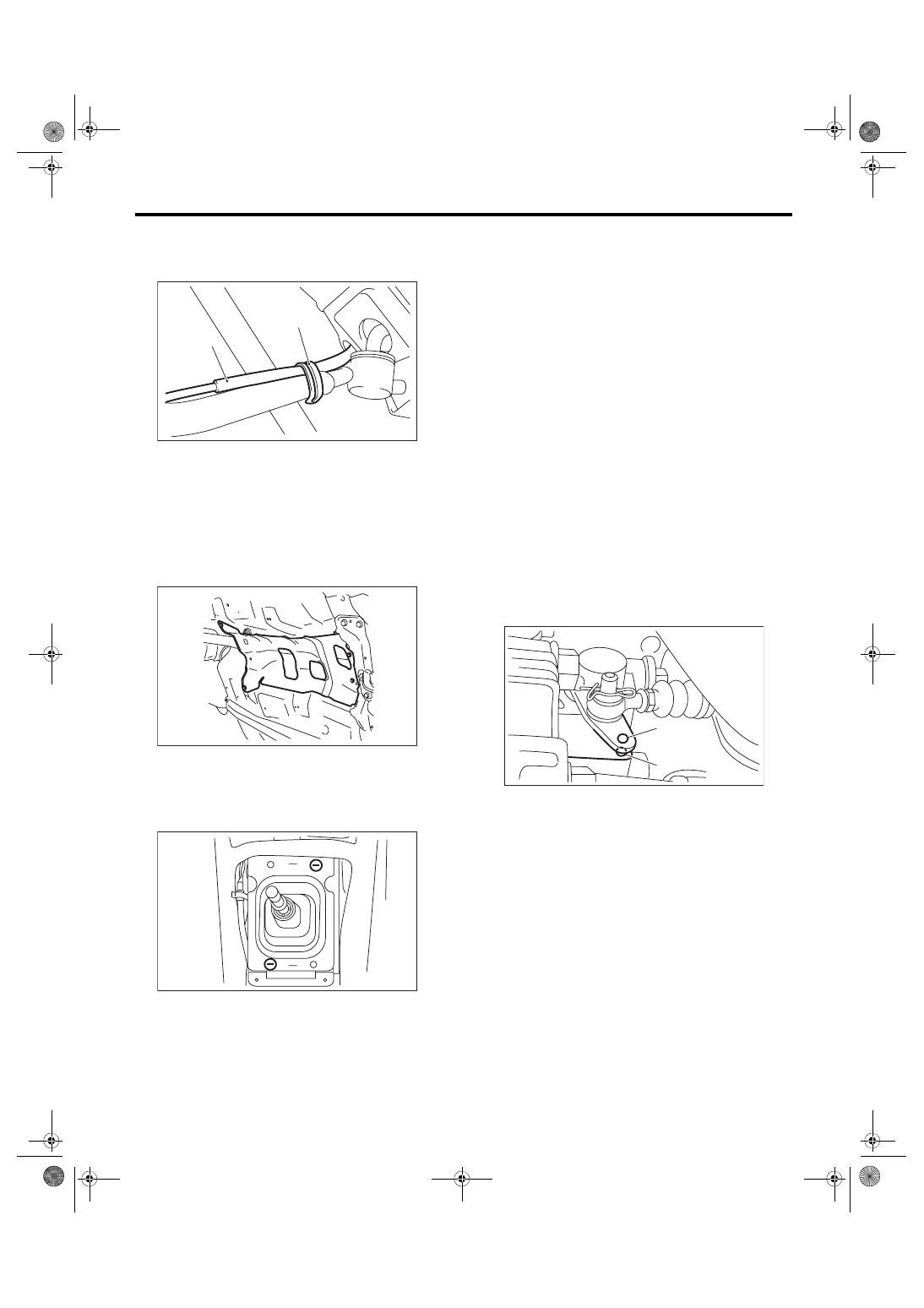
7) Secure the reverse check cable to the stay clip.
NOTE:
Install the reverse check cable on top of the stay.
8) Install the crossmember. <Ref. to 6MT-29, IN-
STALLATION, Transmission Mounting System.>
9) Install the heat shield cover.
Tightening torque:
18 N·m (1.8 kgf-m, 13.3 ft-lb)
10) Install the center exhaust pipe. <Ref. to
EX(STI)-9, INSTALLATION, Center Exhaust
11) Install the boot and insulator assembly, and se-
cure with a clamp.
12) Install the console side cover and console front
panel. <Ref. to EI-54, INSTALLATION, Center
13) Install the console box. <Ref. to EI-51, INSTAL-
14) Install the gear shift knob.
C: INSPECTION
1) Make sure the slider moves smoothly. If it does
not move, adjust the reverse check cable, or check
the slider for damage. <Ref. to CS-27, ADJUST-
2) Check if the gear shifts into reverse when pulling
up the slider. If the gear cannot shift into reverse,
adjust the reverse check cable. <Ref. to CS-27,
ADJUSTMENT, Reverse Check Cable.>
3) Check that the gear does not shift into reverse
when the slider is not pulled up. If the gear shifts
into reverse, adjust or replace the reverse check
cable. <Ref. to CS-27, ADJUSTMENT, Reverse
4) Make sure the hole of extension case is aligned
with that of reverse check lever. If the hole posi-
tions are not aligned, adjust the reverse check ca-
ble. <Ref. to CS-27, ADJUSTMENT, Reverse
Check Cable.>
NOTE:
• Check that the M3 bolt goes through the hole of
reverse check lever and can be inserted into the
hole of extension case.
• When checking visually, confirm that the gap of
hole positions is 0.5 mm (0.02 in) or less.
(A) Reverse check cable
(B) Clip
CS-00243
(A)
(B)
MT-01660
CS-00926
(A) Hole of reverse check lever
(B) Hole of extension case
(A)
(B)
CS-01751
Нет комментариевНе стесняйтесь поделиться с нами вашим ценным мнением.
Текст