Subaru Impreza 3 / Impreza WRX / Impreza WRX STI. Service manual — part 391
CS-15
MT Gear Shift Lever
CONTROL SYSTEMS
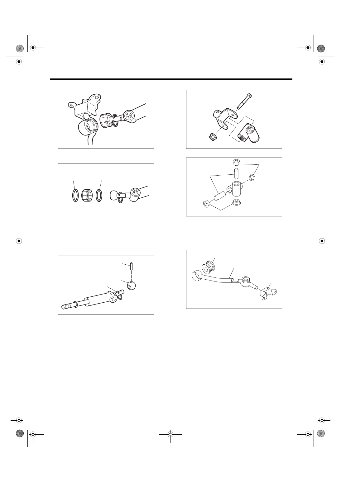
5) Separate the gear shift lever and the stay.
6) Remove the O-ring and bushing from the gear
shift lever.
7) Remove the spring pin, and then remove the
bushing and snap ring.
8) Remove the boss from the joint.
9) Remove the bushing and spacer from the boss.
10) Remove the bushing and cushion rubber from
the stay.
(A) O-ring
(B) Bushing
(A) Spring pin
(B) Bushing
(C) Snap ring
CS-01413
CS-01415
(B)
(A)
(A)
CS-01414
(B)
(A)
(C)
(A) Bushing
(B) Spacer
(A) Bushing
(B) Stay
(C) Cushion rubber
CS-00322
CS-00238
(B)
(A)
(A)
CS-00058
(A)
(B)
(C)
CS-16
MT Gear Shift Lever
CONTROL SYSTEMS
D: ASSEMBLY
NOTE:
• Clean all the parts before assembly.
• Apply NIGTIGHT LYW No. 2 grease or equiva-
lent to each part. <Ref. to CS-3, 6MT GEAR SHIFT
LEVER, COMPONENT, General Description.>
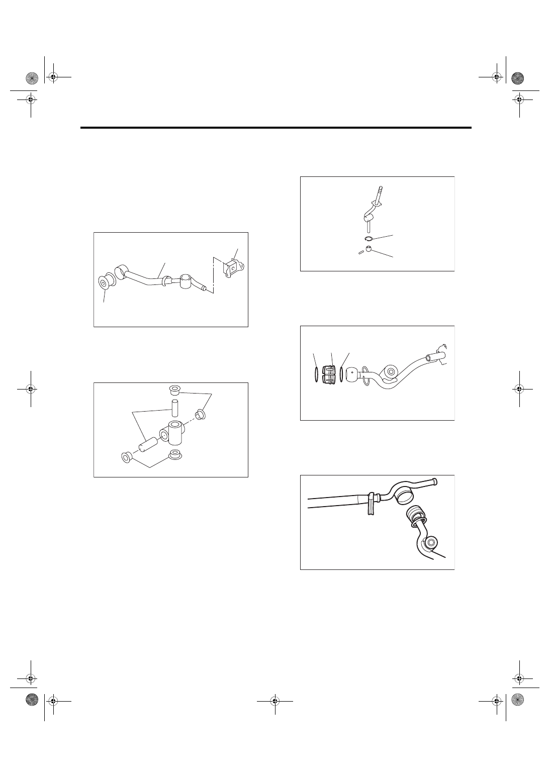
1. STI MODEL
1) Mount the bushing and cushion rubber to the
stay.
2) Install the bushing and spacer to boss.
3) Install the snap ring to gear shift lever and install
the bushing.
NOTE:
Apply grease to the bushing.
4) Apply grease to the bushing and O-ring, and
then install to gear shift lever.
5) Apply sufficient grease into boss, and then install
the gear shift lever to the stay.
(A) Bushing
(B) Stay
(C) Cushion rubber
(A) Bushing
(B) Spacer
CS-00239
(B)
(C)
(A)
CS-00238
(B)
(A)
(A)
(A) Bushing
(B) Snap ring
(A) O-ring
(B) Bushing
CS-00237
(A)
(B)
CS-00236
(A)
(B)
(A)
CS-00235
CS-17
MT Gear Shift Lever
CONTROL SYSTEMS
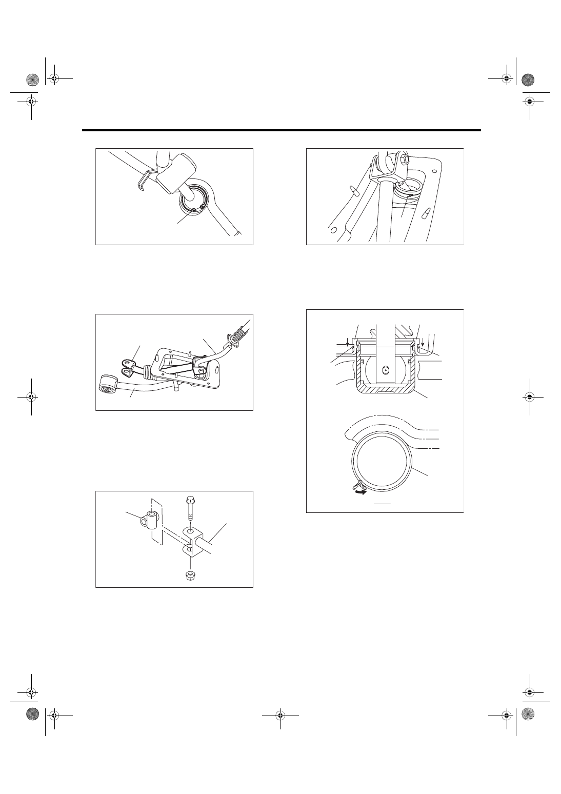
6) Install the snap ring.
7) Insert the gear shift lever and rod into boot hole.
8) Install the rod.
Tightening torque:
12 N·m (1.2 kgf-m, 8.9 ft-lb)
9) Install the boss to the rod.
Tightening torque:
12 N·m (1.2 kgf-m, 8.9 ft-lb)
10) Install a new lock wire.
NOTE:
• Install the lock wire to the stay groove.
• Bend the extra wire to the same direction of lock
wire winding.
(A) Snap ring
(A) Rod
(B) Lever
(C) Stay
(A) Rod
(B) Boss
CS-00234
(A)
CS-00233
(C)
(A)
(B)
CS-00232
(B)
(A)
(A) Lock wire
(A) Inner boot
(B) Lock wire
(C) Stay
CS-00231
(A)
CS-00240
(A)
(A)
(B)
(B)
B
B
(B)
B - B
(C)
CS-18
MT Gear Shift Lever
CONTROL SYSTEMS
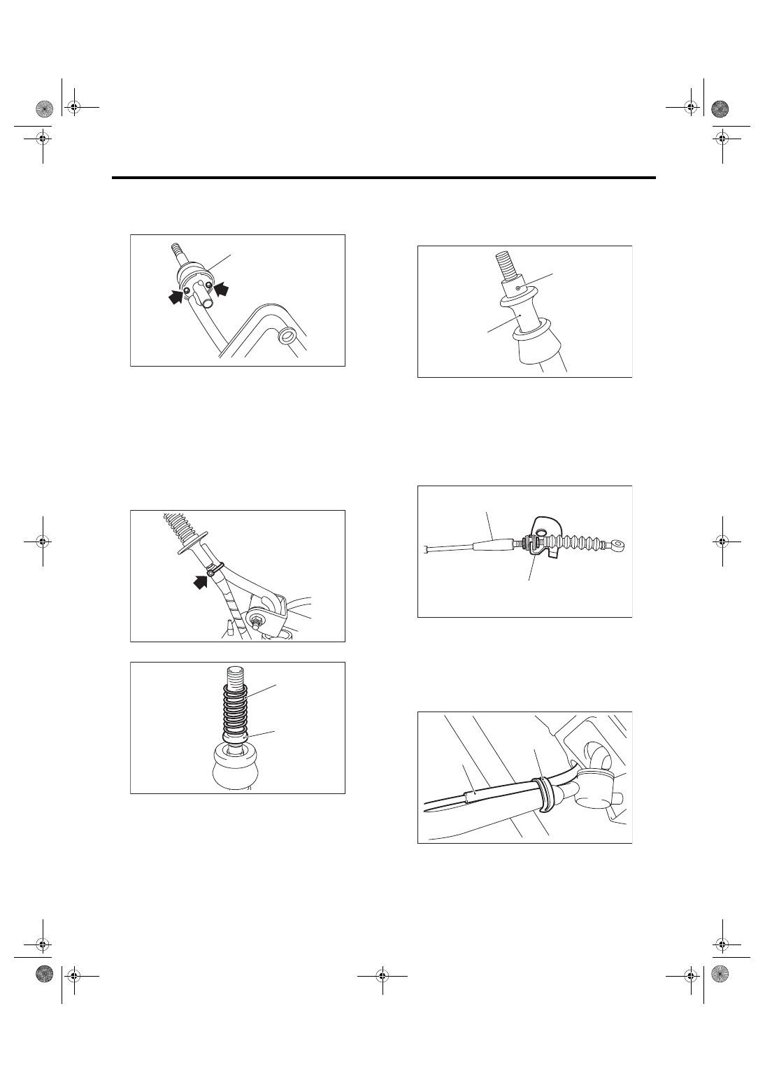
11) Install the holder.
Tightening torque:
1.3 N·m (0.1 kgf-m, 1.0 ft-lb)
12) Insert the reverse check cable into the boot
hole.
13) Insert the reverse check cable into the gear
shift assembly, and fix in place with a band clip.
NOTE:
• Cut the excess band clip.
• Make sure that the reverse check cable is insert-
ed into the gearshift lever with no gaps.
14) Install the seat cushion and spring.
15) Use the spring pin to secure the end of the slid-
er and reverse check cable.
NOTE:
Apply grease to the moving part of slider.
16) Install the reverse check cable to the cable
plate, and tighten the lock nut.
Tightening torque:
6 N·m (0.6 kgf-m, 4.4 ft-lb)
17) Secure the reverse check cable to the stay clip.
NOTE:
Install the reverse check cable on top of the stay.
(A) Holder
(A) Spring
(B) Seat cushion
(A)
CS-00230
CS-00227
CS-00241
(A)
(B)
(A) Slider
(B) Spring pin
(A) Cable plate
(B) Reverse check cable
(A) Reverse check cable
(B) Clip
CS-00225
(A)
(B)
CS-00228
(A)
(B)
CS-00243
(A)
(B)
Нет комментариевНе стесняйтесь поделиться с нами вашим ценным мнением.
Текст