Subaru Impreza 3 / Impreza WRX / Impreza WRX STI. Service manual — part 576
PS-25
Steering Gearbox
POWER ASSISTED SYSTEM (POWER STEERING)
D: ASSEMBLY
1. RACK HOUSING ASSEMBLY
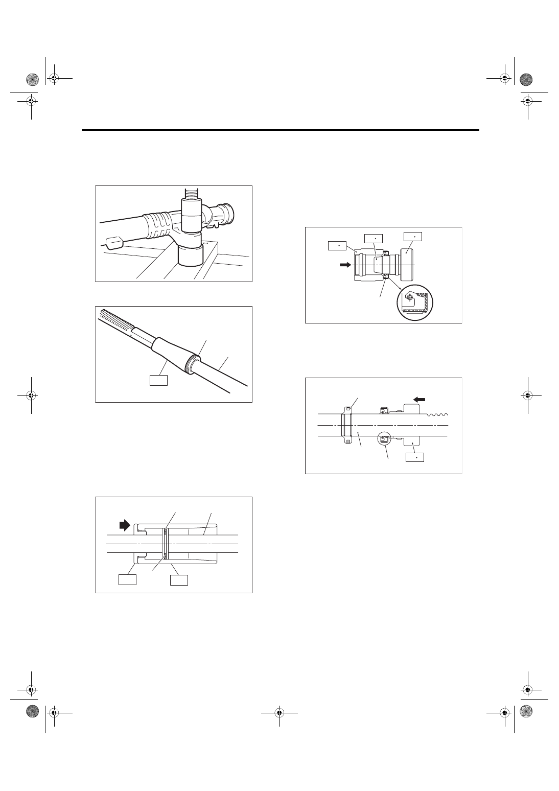
1) Using a press, install the bushing to gearbox in-
stallation portion.
2) Insert the ST to rack.
ST 34199AG040 GUIDE
3) Install the seal ring and O-ring to piston portion
of rack.
4) Using the ST, form the seal ring properly.
ST1 34199AG080 FORMER PISTON
ST2 34199AG060 GUIDE G (26)
5) Using the ST A and ST B, attach the oil seal to
ST C.
ST 34199FE040 INSTALLER A, B, C
• INSTALLER A: 34199FE070
• INSTALLER B: 34199FE080
• INSTALLER C: 34199FE090
NOTE:
Face the oil seal in the direction as shown in the fig-
ure.
6) Insert the ST C with oil seal assembled from the
gear side of rack. Remove the oil seal from ST C
near piston, and then remove the ST C from rack.
(1) Seal ring
(2) Rack
(3) O-ring
(1) Seal ring
(2) Rack
(3) O-ring
PS-00519
PS-01210
ST
(1),(3)
(2)
PS-01211
(2)
(1)
ST1
ST2
(3)
(A) Oil seal
(A) Oil seal
(B) Rack
(C) Piston
ST C
ST B
ST A
(A)
PS-01000
ST C
(A)
(B)
(C)
PS-01001
PS-26
Steering Gearbox
POWER ASSISTED SYSTEM (POWER STEERING)
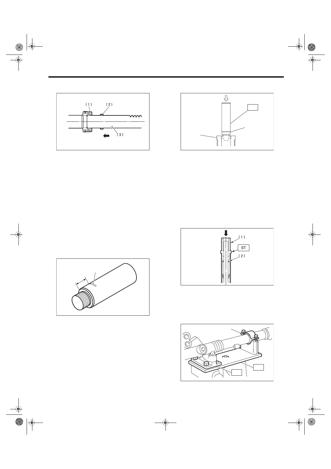
7) Install the back-up ring from the gear side of
rack.
8) Check the threaded end of holder and gearbox
cylinder end for burrs, damage, etc. Correct if
faulty.
9) Apply a coat of grease to the grooves in rack,
sliding surface of sleeve and sealing surface of pis-
ton. Then insert the rack into steering body from
cylinder side.
10) Temporarily tighten a new holder to the gear-
box cylinder.
11) Put a mark at the specified position measured
from the end surface of ST, as shown in the figure.
Specified position:
15 mm (0.59 in)
ST 34199XA030 INSTALLER & REMOVER
12) Set the ST to the end of rack.
ST 34199XA030 INSTALLER & REMOVER
13) Using a press, press-fit until the mark on the ST
is aligned with the end surface of the holder.
14) Remove the ST and holder.
15) Insert the outer side oil seal into the rack using
the same procedure as steps 5) and 6).
ST 34199FE040 INSTALLER A, B, C
• INSTALLER A: 34199FE070
• INSTALLER B: 34199FE080
• INSTALLER C: 34199FE090
16) Put the ST and pipe through the rack, and
press-fit the outer side oil seal using a press.
ST 34199AG010 INSTALLER
17) Secure the gearbox in a vise using ST.
ST1 926200000
STAND
ST2 34199AG000 BOSS D
(1) Oil seal
(2) Back-up ring
(3) Rack
(1) 15 mm (0.59 in)
(2) Place a mark
PS-00077
PS-00851
(1)
(2)
(1) Mark
(2) Holder
(1) Pipe
(2) Outer side oil seal
(1) Clamp
PS-00522
ST
(1)
(2)
PS-00852
(1)
ST1
ST2
PS-00492
PS-27
Steering Gearbox
POWER ASSISTED SYSTEM (POWER STEERING)
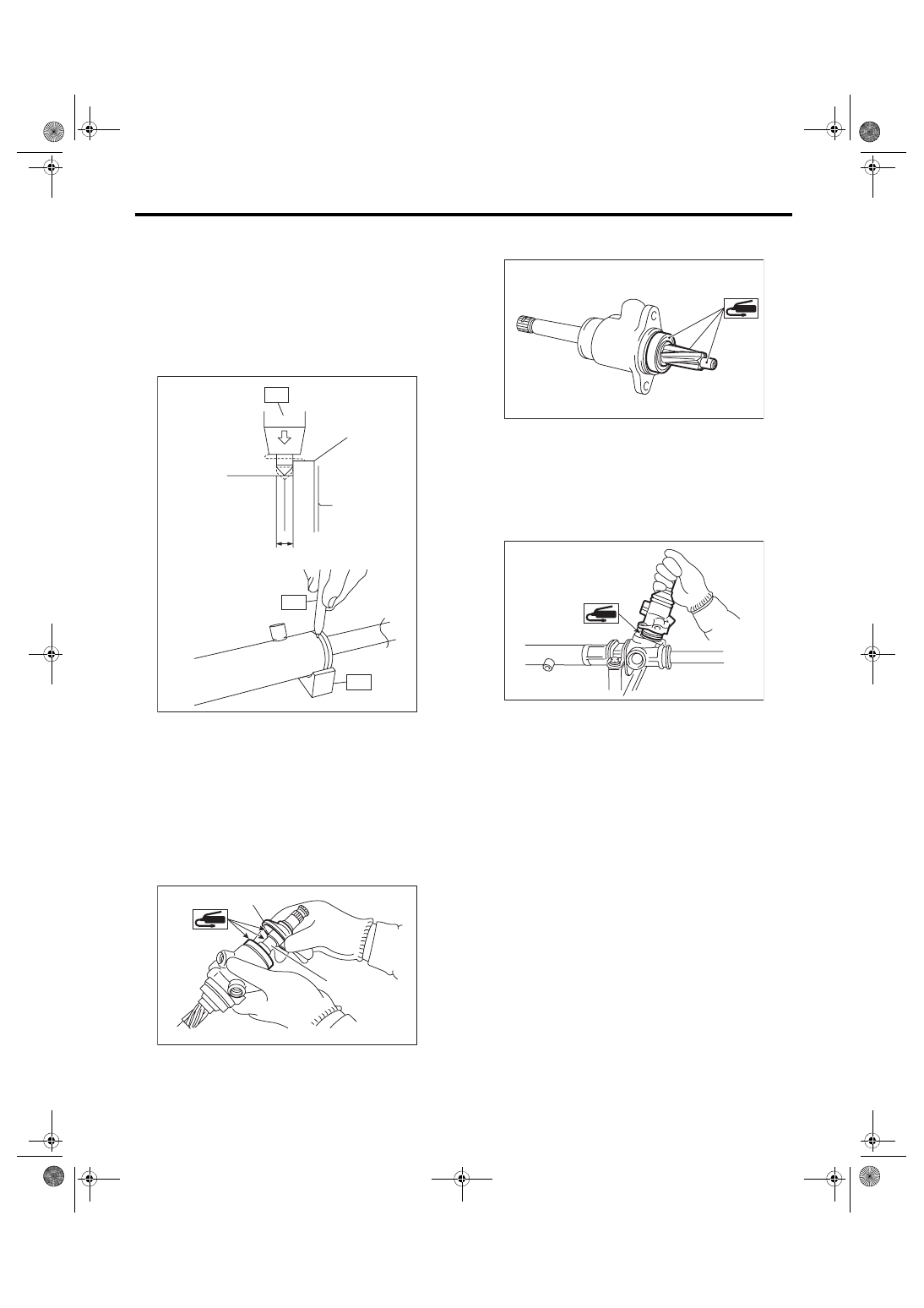
18) Tighten the holder.
Tightening torque:
70 N·m (7.1 kgf-m, 51.6 ft-lb)
19) Using the ST, crimp so that the diameter of
punch hole is 2 — 2.5 mm (0.08 — 0.10 in) and is
aligned to the position of 2 mm (0.08 in) from gear-
box cylinder end surface.
ST1 34099FA060
PUNCH HOLDER
ST2 34199FE020
BASE
20) Put a vinyl tape around the spline portion and
apply genuine grease to the dust cover and fill it to
the clearance between pinion shaft and housing,
then install the valve assembly.
CAUTION:
Be sure to install the dust cover to groove of
shaft.
21) Apply the genuine grease to the edge and body
of pinion gear and bearing of valve assembly.
22) Apply grease to a new O-ring and attach it to
the valve assembly. Insert the valve assembly into
place while facing the rack teeth toward pinion.
CAUTION:
Check that the needle bearing is not damaged.
Replace with a new steering gearbox if damage
is found.
23) Tighten the bolts alternately to secure the valve
assembly.
CAUTION:
Be sure to alternately tighten the bolts.
Tightening torque:
20 N·m (2.0 kgf-m, 14.8 ft-lb)
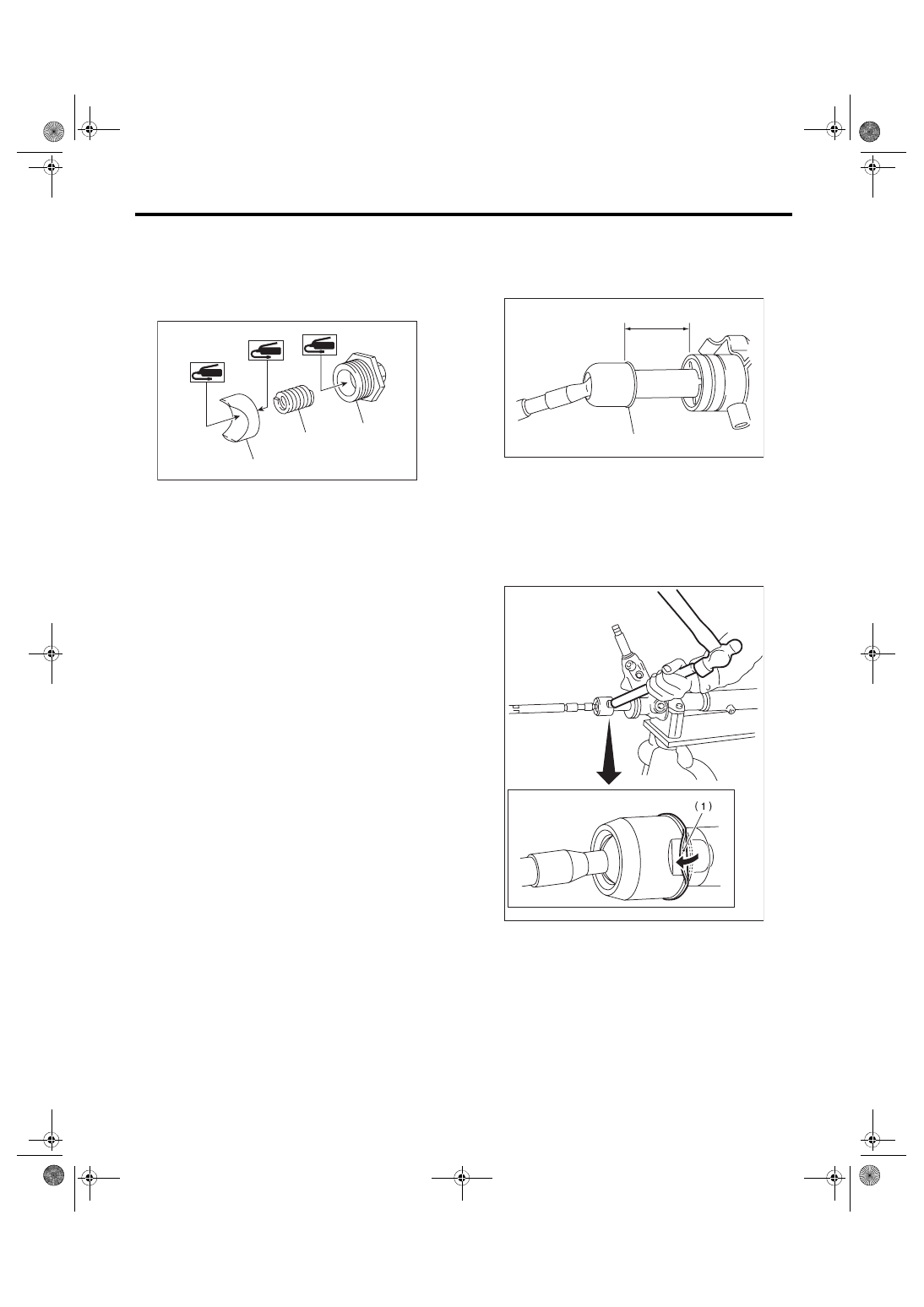
24) Temporarily tighten the tie-rod to the rack end,
and then operate the rack from lock to lock for two
or three times to make it fit in.
CAUTION:
Operating the rack from lock to lock without in-
stalling tie-rods may damage the oil seal. Al-
ways install the left and right tie-rods.
25) Apply liquid gasket to 1/3 or more of entire pe-
rimeter of adjusting screw thread.
Liquid gasket:
THREE BOND 1102 or THREE BOND 1215
(A) Holder
(B) 2 mm (0.08 in)
(1) Dust cover
(2) Groove
(A)
(B)
ST1
ST2
ST1
PS-00859
PS-01675
(1)
(2)
PS-01674
PS-01673
PS-28
Steering Gearbox
POWER ASSISTED SYSTEM (POWER STEERING)
26) Apply a coat of grease to the sliding surface of
sleeve and seating surface of spring, and then in-
sert the sleeve into steering body.
Charge the adjusting screw with grease, and then
insert the spring into adjusting screw. Then install
on the steering body.
27) Tighten the adjusting screw to the specified
torque, then loosen it.
Tightening torque:
25 N·m (2.5 kgf-m, 18.4 ft-lb)
28) Tighten the adjusting screw to the specified
torque, then loosen it within 20°.
Tightening torque:
5.9 N·m (0.6 kgf-m, 4.4 ft-lb)
29) Remove the tie-rod.
30) Adjust the turning resistance of gearbox so that
it is within specification using adjusting screw.
<Ref. to PS-36, TURNING RESISTANCE OF
GEARBOX, INSPECTION, Steering Gearbox.>
31) Attach the lock nut into adjusting screw, and
while holding the adjusting screw with wrench,
tighten the lock nut using ST.
ST 926230000
SPANNER
Tightening torque (lock nut):
25 N·m (2.5 kgf-m, 18.4 ft-lb)
NOTE:
Hold the adjusting screw with a wrench to prevent it
from turning while tightening lock nut.
32) Extend the rack approx. 40 mm (1.57 in) from
steering body.
33) Install the tie-rod and new lock washer into
rack.
Tightening torque:
93 N·m (9.5 kgf-m, 68.6 ft-lb)
34) Bend the lock washer and crimp it.
CAUTION:
Be careful not to scratch the rack when crimp-
ing lock washer.
(1) Sleeve
(2) Spring
(3) Adjusting screw
(2)
(1)
(3)
PS-00167
(1) Lock washer
(2) Approx. 40 mm (1.57 in)
(1) Lock washer
PS-00439
(2)
(1)
PS-00093
Нет комментариевНе стесняйтесь поделиться с нами вашим ценным мнением.
Текст