Subaru Impreza 3 / Impreza WRX / Impreza WRX STI. Service manual — part 575
PS-21
Steering Gearbox
POWER ASSISTED SYSTEM (POWER STEERING)
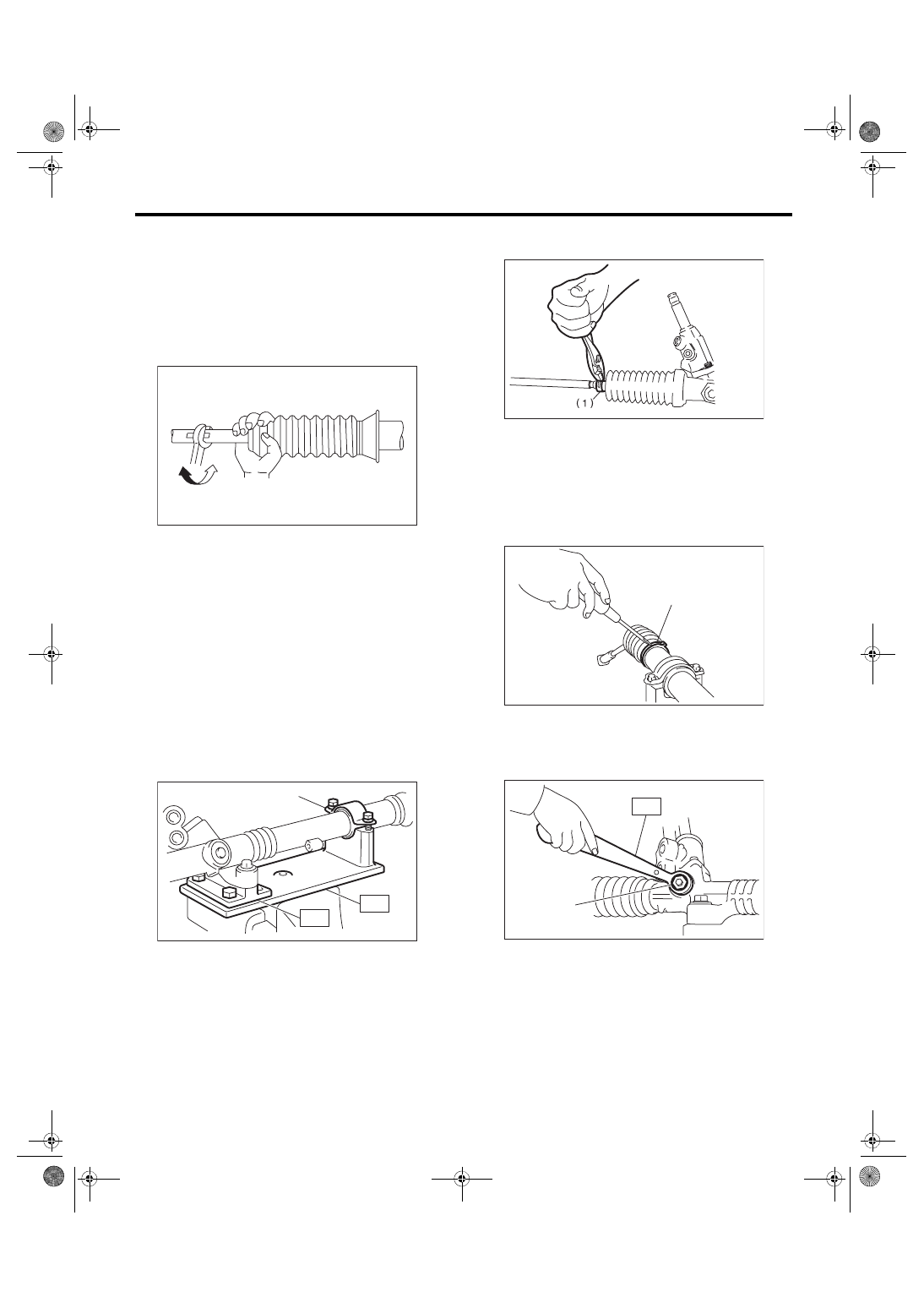
23) After adjusting toe-in and steering angle, tight-
en the lock nut on tie-rod end.
Tightening torque:
85 N·m (8.7 kgf-m, 62.7 ft-lb)
NOTE:
When adjusting toe-in, hold the boot as shown to
prevent it from being rotated or twisted. If it be-
comes twisted, straighten it.
C: DISASSEMBLY
1. RACK HOUSING ASSEMBLY
1) Disconnect the four pipes from gearbox.
NOTE:
Remove the pipes C and D, which are fixed to
clamp plate, as a unit.
2) Secure the gearbox removed from vehicle in a
vise using ST.
CAUTION:
Secure the gearbox assembly in a vise using ST
as shown. Do not affix the gearbox to the vice
without this ST.
ST1 926200000
STAND
ST2 34199AG000 BOSS D
3) Remove the tie-rod end and lock nut from gear-
box.
4) Remove the small clip from the boot using pliers,
and then move the boot to tie-rod end side.
5) Using a flat tip screwdriver, remove the band
from boot.
NOTE:
Replace the boot if there is damage, cracks or de-
terioration.
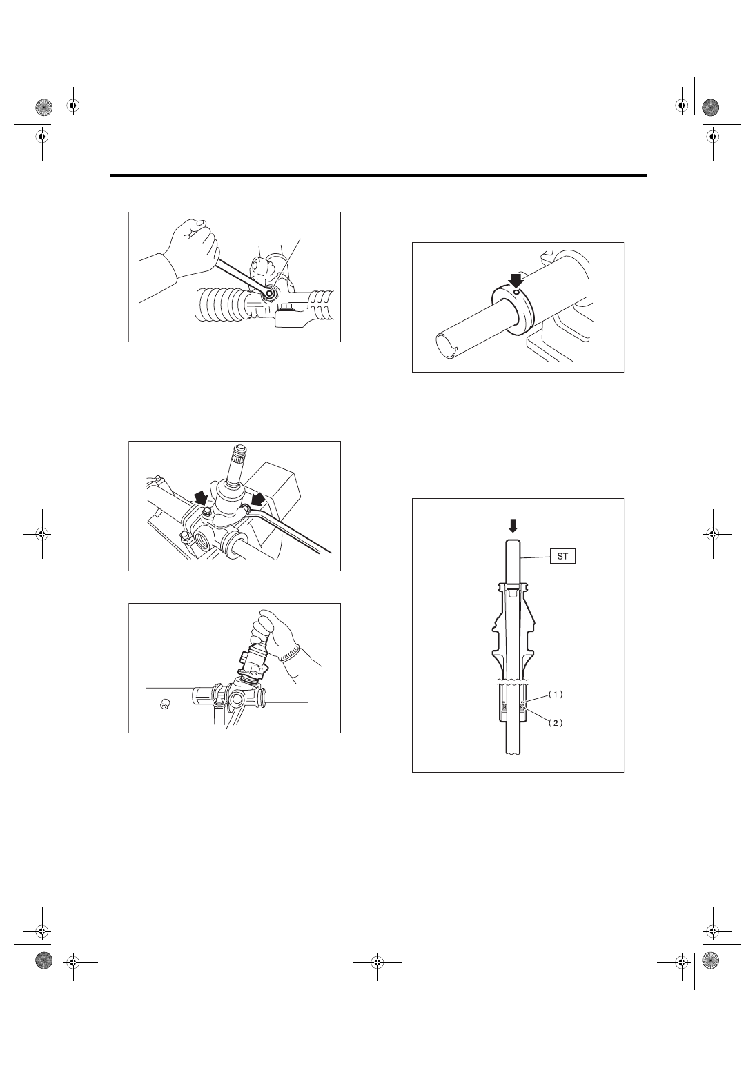
6) Using the ST, loosen the lock nut.
ST 926230000
SPANNER
(1) Clamp
PS-00051
(1)
ST1
ST2
PS-00492
(1) Clip
(1) Band
(1) Lock nut
PS-00053
PS-00509
(1)
ST
(1)
PS-00494
PS-22
Steering Gearbox
POWER ASSISTED SYSTEM (POWER STEERING)
7) Tighten the adjusting screw until it can no longer
be tightened.
8) Remove the tie-rod.
9) Loosen the adjusting screw, and remove the
spring and sleeve.
10) Remove the two bolts securing valve assem-
bly.
11) Carefully draw out the input shaft and remove
the valve assembly.
12) Using a drill, release the crimping of holder.
CAUTION:
Make a hole of 2 mm (0.08 in) depth using a drill
with 3 mm (0.12 in) diameter.
13) Remove the holder.
14) Attach the ST on the valve side of rack, and
press out the outer side oil seal and rack while tak-
ing care that the rack and the steering body inner
surface do not come into contact with each other.
ST 34199XA030 INSTALLER & REMOVER
NOTE:
Block the pipe connection of steering body to pre-
vent fluid from flowing out.
(1) Adjusting screw
(1)
PS-00495
PS-00116
PS-00117
(1) Rack piston
(2) Outer side oil seal
PS-00516
PS-00064
PS-23
Steering Gearbox
POWER ASSISTED SYSTEM (POWER STEERING)
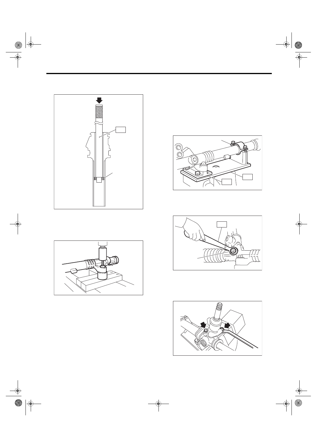
15) Insert the ST from pinion housing side and re-
move the oil seal and back-up ring using a press.
ST 34099PA010 OIL SEAL REMOVER
16) Using a press, remove the bushing of gearbox
installation portion.
2. CONTROL VALVE
1) Disconnect the four pipes from gearbox.
2) Secure the gearbox removed from vehicle in a
vise using ST.
CAUTION:
Secure the gearbox assembly in a vise using ST
as shown. Do not affix the gearbox to the vice
without this ST.
ST1 926200000
STAND
ST2 34199AG000 BOSS D
3) Using the ST, loosen the lock nut.
ST 926230000
SPANNER
4) Loosen the adjusting screw, and remove the
spring and sleeve.
5) Remove the two bolts securing valve assembly.
(1) Press
(2) Oil seal
PS-00138
(2)
(1)
ST
PS-00517
(1) Clamp
(1) Lock nut
(1)
ST1
ST2
PS-00492
ST
(1)
PS-00494
PS-00116
PS-24
Steering Gearbox
POWER ASSISTED SYSTEM (POWER STEERING)
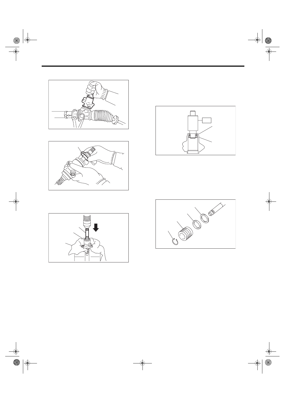
6) Carefully draw out the input shaft and remove
the valve assembly.
7) Put a vinyl tape around the spline portion, and
slide the dust cover to remove.
8) Using a press, remove the pinion & valve as-
sembly from valve housing.
9) Using the ST and a press, remove the bushing
and oil seal from the valve housing.
CAUTION:
• Do not apply a force to the end surface of
valve housing.
• Do not reuse the oil seal after removal.
ST 34199AG090 INSTALLER & REMOVER
10) Using a snap ring pliers, remove the snap ring,
valve, oil seal and back-up washer.
CAUTION:
Be careful not to scratch the pinion and valve
assembly.
(1) Dust cover
(1) Pinion & valve ASSY
(2) Valve housing
(3) Cloth
PS-00143
PS-00144
(1)
(2)
(3)
(1)
PS-00149
(1) Oil seal
(2) Bushing
(1) Snap ring
(2) Valve
(3) Oil seal
(4) Back-up ring
(2)
(1)
ST
PS-00855
PS-00518
(1)
(2)
(3)
(4)
Нет комментариевНе стесняйтесь поделиться с нами вашим ценным мнением.
Текст