Subaru Impreza 3 / Impreza WRX / Impreza WRX STI. Service manual — part 574
PS-17
Steering Column
POWER ASSISTED SYSTEM (POWER STEERING)
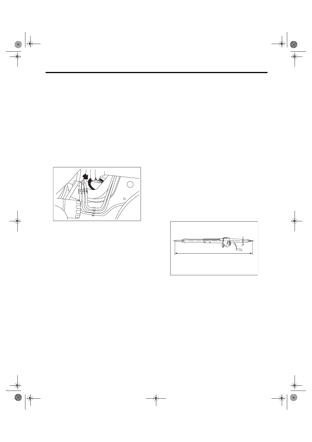
9) Pull out the steering shaft assembly from the
hole on toe board.
CAUTION:
• Always remove the universal joint before re-
moving the steering column installation bolt to
avoid damage to the universal joint.
• Be sure to remove the universal joint before
removing the parts, if the relative position be-
tween steering shaft and gearbox changes
when removing steering shaft assembly or
when lowering it and gearbox for servicing oth-
er parts.
• Do not loosen the tilt lever when the steering
column is not secured to the vehicle.
B: INSTALLATION
1) Install the grommet to the toe board.
2) Insert the end of the steering shaft into the toe
board grommet.
3) With the tilt lever secured, tighten the steering
shaft mounting bolts under instrument panel.
Tightening torque:
20 N·m (2.0 kgf-m, 14.8 ft-lb)
4) Connect all the connectors under the instrument
panel.
5) Connect the airbag system connector at the har-
ness spool.
NOTE:
Make sure to apply double lock.
6) Install the instrument panel lower cover with tilt
lever held in the lowered position.
7) Install the universal joint. <Ref. to PS-14, IN-
8) Align the center position of the roll connector.
<Ref. to AB-27, ADJUSTMENT, Roll Connector.>
9) Install the steering wheel. <Ref. to PS-13, IN-
STALLATION, Steering Wheel.>
CAUTION:
Insert the roll connector guide pin into the
guide hole on lower end of steering wheel sur-
face to prevent damage.
C: DISASSEMBLY
Remove the three screws securing the upper steer-
ing column covers, and the two screws securing
the combination switch, and then remove related
parts.
D: ASSEMBLY
Insert the combination switch to the upper column
shaft, and install the upper column cover. Then
route the ignition key harness and combination
switch harness between the column cover mount-
ing bosses.
CAUTION:
Do not overtorque the screw.
Tightening torque:
1.2 N·m (0.12 kgf-m, 0.9 ft-lb)
E: INSPECTION
1. BASIC INSPECTION
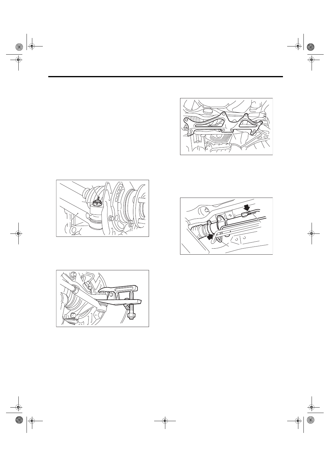
Measure the overall length of steering column. If
not within specification, replace it.
Standard: Overall length L
Tilt and telescopic column (measure while min-
imized)
818.6
+1.5
–1.5
mm (32.23
+0.059
–0.059
in)
2. INSPECTION OF AIRBAG SYSTEM
Refer to “Airbag System” for airbag inspection pro-
cedure. <Ref. to AB-15, INSPECTION, Driver’s Air-
PS-00041
PS-00491
L
PS-18
Steering Gearbox
POWER ASSISTED SYSTEM (POWER STEERING)
5. Steering Gearbox
A: REMOVAL
1) Set the vehicle on a lift.
2) Disconnect the ground cable from battery.
3) Loosen the front wheel nuts.
4) Lift up the vehicle, and then remove the front
wheels.
5) Remove the under cover. <Ref. to EI-28, RE-
6) Remove the front exhaust pipe assembly. <Ref.
to EX(STI)-6, REMOVAL, Front Exhaust Pipe.>
WARNING:
Be careful not to burn yourself because the ex-
haust pipe is hot.
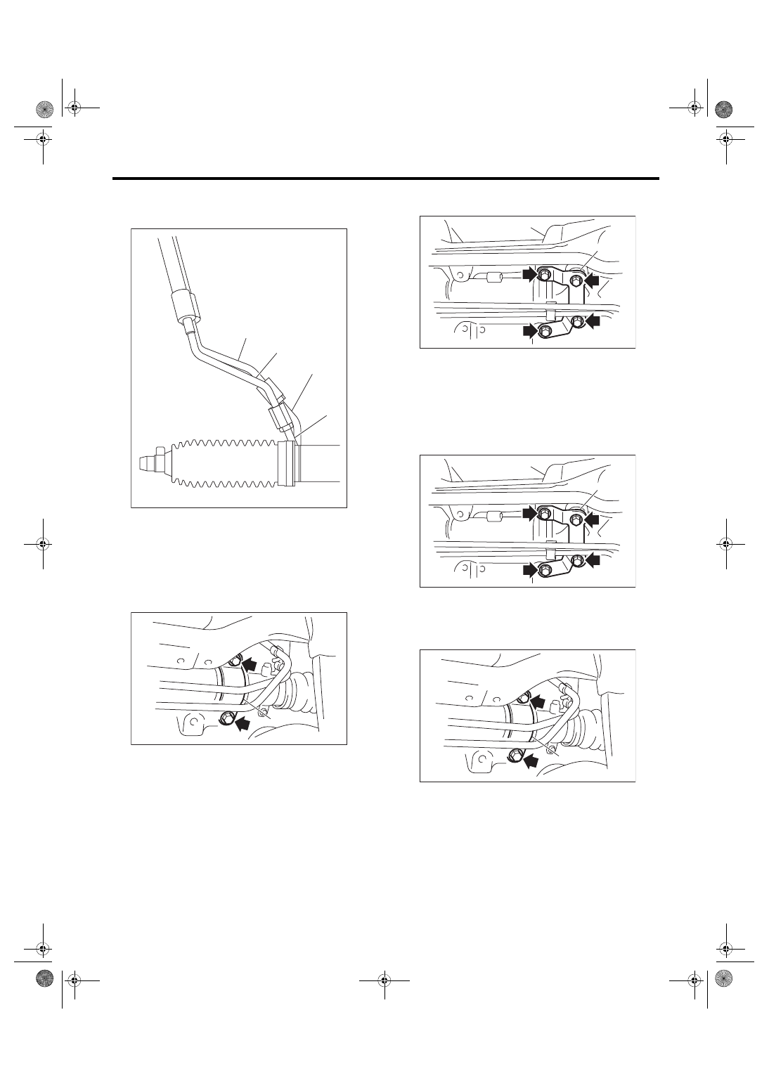
7) Remove the cotter pin and castle nut securing
the tie-rod end.
8) Using a puller, remove the tie-rod.
9) Remove the front crossmember support plate
and front stabilizer. <Ref. to FS-17, REMOVAL,
10) Remove the one pipe joint at the center of the
gearbox, and connect the vinyl hose to the pipe and
the joint. Discharge the fluid by turning the steering
wheel fully clockwise and counterclockwise. Dis-
charge the fluid similarly from other pipes.
11) Remove the universal joint. <Ref. to PS-14,
(A) Cotter pin
(B) Castle nut
(C) Tie-rod end
DS-00042
(C)
(B)
(A)
DS-00043
(1) Front crossmember support plate
(1) Pipe A
(2) Pipe B
PS-00445
(1)
(2)
PS-00553
(1)
PS-19
Steering Gearbox
POWER ASSISTED SYSTEM (POWER STEERING)
12) Disconnect the feed pipe from the pressure
hose first, then disconnect the return pipe from the
return hose.
13) Remove the clamp bolts securing the gearbox
to the crossmember, and remove the clamp.
14) Remove the bolts which secure the gearbox
bracket, and remove the stiffener and gearbox.
B: INSTALLATION
1) Insert the gearbox into crossmember, being
careful not to damage gearbox boot.
2) Install the gearbox and stiffener. Temporarily
tighten the bolts.
3) Insert bolts through the clamp to temporarily
tighten the gearbox to the crossmember bracket.
(1) Feed pipe
(2) Return pipe
(3) Pressure hose
(4) Return hose
(1) Clamp
PS-00538
(4)
(3)
(2)
(1)
PS-00554
(1)
(1) Stiffener
(1) Stiffener
(1) Clamp
(1)
PS-00555
(1)
PS-00555
PS-00554
(1)
PS-20
Steering Gearbox
POWER ASSISTED SYSTEM (POWER STEERING)
4) Tighten the bolts temporarily holding the gear-
box clamp and bracket together to the specified
torque.
Tightening torque:
60 N·m (6.1 kgf-m, 44.3 ft-lb)
5) Connect the return pipe to the return hose and
then connect the feed pipe to the pressure hose.
Tightening torque:
15 N·m (1.5 kgf-m, 11.1 ft-lb)
6) Install the universal joint. <Ref. to PS-14, IN-
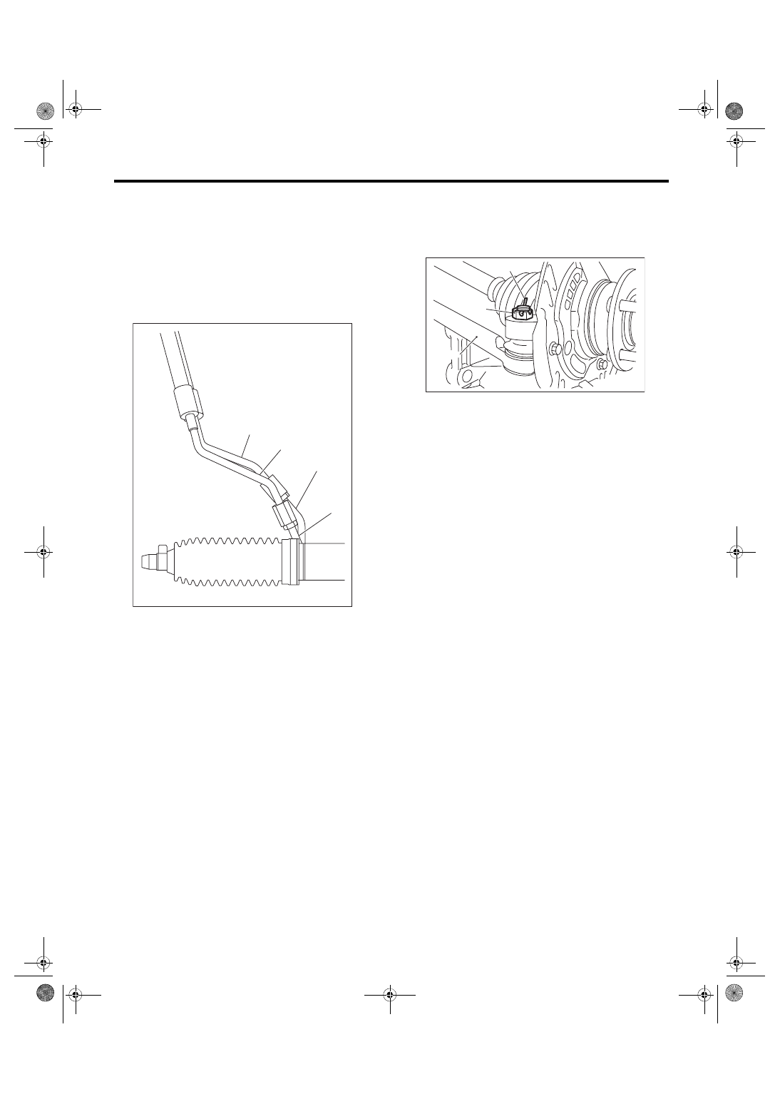
7) Connect the tie-rod end and knuckle arm, and
tighten with castle nut.
CAUTION:
When connecting, do not hit the cap at the bot-
tom of tie-rod end with hammer.
Castle nut tightening torque:
27 N·m (2.8 kgf-m, 19.9 ft-lb)
8) After tightening the castle nut to the specified
tightening torque, tighten it further within 60° until
the cotter pin hole is aligned with slot in the nut. Fit
the cotter pin into the nut, and then bend the pin to
lock.
9) Install the front stabilizer. <Ref. to FS-17, IN-
STALLATION, Front Stabilizer.>
10) Install the front crossmember support plate.
11) Install the front exhaust pipe assembly. <Ref.
to EX(STI)-6, INSTALLATION, Front Exhaust
12) Install the under cover. <Ref. to EI-28, INSTAL-
13) Install the front wheels.
14) Tighten the wheel nuts to the specified torque.
Tightening torque:
100 N·m (10.2 kgf-m, 73.8 ft-lb)
15) Lower the vehicle.
16) Remove the steering wheel. <Ref. to PS-13,
17) Align the center position of the roll connector.
<Ref. to AB-27, ADJUSTMENT, Roll Connector.>
18) Install the steering wheel. <Ref. to PS-13, IN-
19) Connect the battery ground terminal.
20) Pour fluid into the oil tank, and bleed air. <Ref.
to PS-51, Power Steering Fluid.>
21) Check for fluid leaks.
22) Check the fluid level in oil tank.
(1) Feed pipe
(2) Return pipe
(3) Pressure hose
(4) Return hose
PS-00538
(4)
(3)
(2)
(1)
(A) Cotter pin
(B) Castle nut
(C) Tie-rod end
DS-00042
(C)
(B)
(A)
Нет комментариевНе стесняйтесь поделиться с нами вашим ценным мнением.
Текст