Subaru Impreza 3 / Impreza WRX / Impreza WRX STI. Service manual — part 441
6MT-101
Front Differential Assembly
MANUAL TRANSMISSION AND DIFFERENTIAL
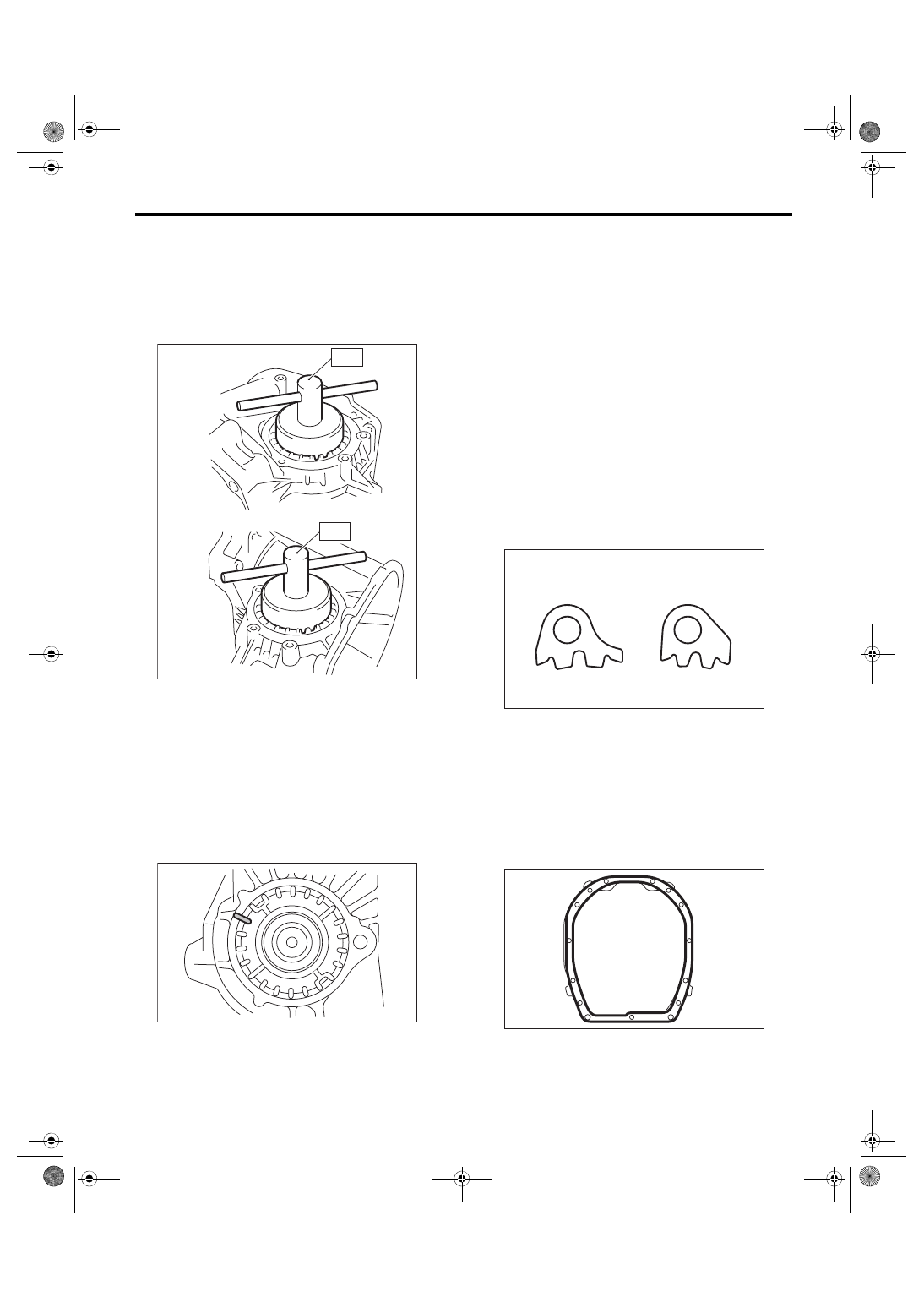
4) Install the differential side retainers to both
sides, using the ST.
ST1 18630AA010
WRENCH COMPL RETAIN-
ER (RH SIDE)
ST2 18630AA000
WRENCH ASSY (LH SIDE)
NOTE:
Be careful not to damage the oil seal.
5) Inspect and adjust the hypoid gear backlash.
<Ref. to 6MT-104, HYPOID GEAR BACKLASH,
INSPECTION, Front Differential Assembly.>
6) Inspect and adjust the tooth contact. <Ref. to
6MT-98, ADJUSTMENT, Drive Pinion Shaft As-
7) Mark the mating positions of the left and right
side retainers and the clutch housing.
8) Remove the differential side retainers from both
sides.
NOTE:
When removing the side retainer, record how many
times it was turned to remove.
9) Install new O-rings to the side retainers on both
sides.
10) Attach the differential side retainers to both
sides.
NOTE:
When attaching, turn the side retainer the same
number of turns it took to remove, and align the
marks.
11) Install the lock plate.
Tightening torque:
25 N·m (2.5 kgf-m, 18.4 ft-lb)
NOTE:
Be careful not to confuse the left and right side lock
plates.
12) Remove any remaining liquid gasket from the
clutch housing and adapter plate.
13) Apply liquid gasket to the clutch housing.
Liquid gasket:
THREE BOND 1215 (Part No. 004403007) or
equivalent
(A) LH side
(B) RH side
(A)
(B)
MT-00657
ST1
ST2
MT-00658
(A) LH
(B) RH
MT-00659
(A)
(B)
MT-00532
6MT-102
Front Differential Assembly
MANUAL TRANSMISSION AND DIFFERENTIAL
14) Install the drive pinion shaft assembly. <Ref. to
6MT-94, INSTALLATION, Drive Pinion Shaft As-
15) Install the individual gear assemblies all at
once. <Ref. to 6MT-66, INSTALLATION, Main
16) Install the transmission case. <Ref. to 6MT-60,
INSTALLATION, Transmission Case.>
17) Install the center differential. <Ref. to 6MT-57,
INSTALLATION, Center Differential.>
18) Install the transfer driven gear. <Ref. to 6MT-
55, INSTALLATION, Transfer Driven Gear.>
19) Install the extension case. <Ref. to 6MT-43, IN-
20) Install the neutral position switch, back-up light
switch and harness. <Ref. to 6MT-41, INSTALLA-
TION, Neutral Position Switch.> <Ref. to 6MT-39,
INSTALLATION, Back-up Light Switch.>
21) Install the manual transmission assembly to the
vehicle. <Ref. to 6MT-33, INSTALLATION, Manual
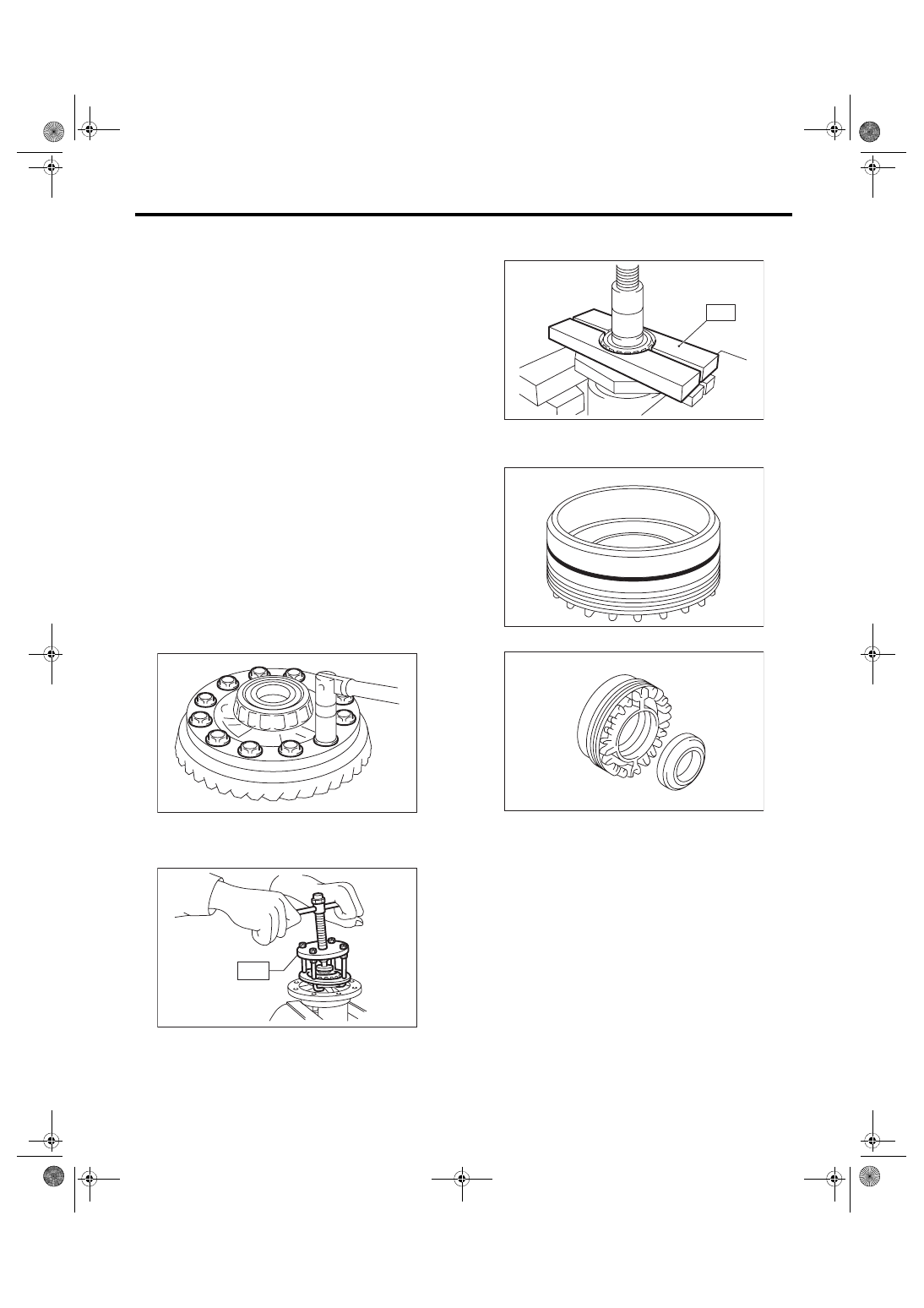
C: DISASSEMBLY
1. DIFFERENTIAL CASE
1) Fix the differential assembly on a vice, and re-
move the hypoid driven gear.
ST 18270KA020 SOCKET (E20)
2) Remove the side bearing of the hypoid driven
gear using the ST.
ST 399527700
PULLER SET
3) Using the ST, remove the roller bearing.
ST 498077000
REMOVER
2. SIDE RETAINER
1) Remove the O-ring.
2) Remove the oil seal.
MT-00660
MT-00663
ST
MT-00665
ST
MT-03038
MT-03040
6MT-103
Front Differential Assembly
MANUAL TRANSMISSION AND DIFFERENTIAL
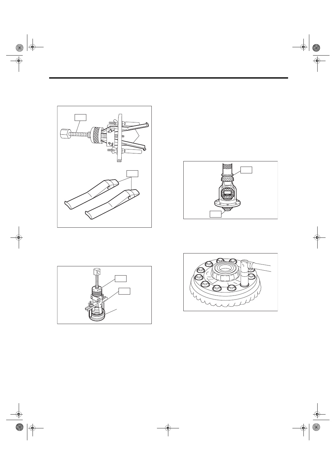
3) Remove the claw of ST1, and attach the claw of
ST2.
ST1 398527700
PULLER ASSY
ST2 18760AA000
CLAW
4) Remove the bearing outer race from the side re-
tainer, using the ST.
ST1 398527700
PULLER ASSY
ST2 18760AA000
CLAW
D: ASSEMBLY
1. DIFFERENTIAL CASE
1) Use the ST to attach the RH and LH bearing in-
ner races to the differential case.
ST1 398437700
INSTALLER
ST2 398497701
SEAT
CAUTION:
Do not apply pressure in excess of 20 kN (2.0
ton, 2.2 US ton, 2.0 Imp ton).
NOTE:
Always replace inner races and outer races as a
set.
2) Attach the hypoid driven gear to the differential
case.
ST 18270KA020 SOCKET (E20)
Tightening torque:
69 N·m (7.0 kgf-m, 50.9 ft-lb)
(A) Claw
(A) Side retainer
MT-00668
(A)
ST2
ST1
MT-00669
(A)
ST2
ST1
MT-00670
ST1
ST2
MT-00660
6MT-104
Front Differential Assembly
MANUAL TRANSMISSION AND DIFFERENTIAL
2. SIDE RETAINER
NOTE:
Install the oil seal and O-ring of side retainer after
the adjustment of backlash and tooth contact.
1) Install the bearing outer race to side retainer.
2) Using the ST, install the oil seal.
ST 18675AA000
DIFFERENTIAL SIDE OIL
SEAL INSTALLER
NOTE:
• Use a new oil seal.
• Apply oil to the oil seal lips.
3) Install the O-ring.
NOTE:
Use new O-rings.
E: INSPECTION
Repair or replace the differential in the following
cases:
• If gears are damaged, seized, or are excessively
worn.
• If differential case sliding surfaces are damaged,
seized, or are excessively worn.
• If there is damage, rust or wear in the bearings or
bearing locations.
• If the bearing does not rotate smoothly or an ab-
normal noise is emitted when turning.
1. HYPOID GEAR BACKLASH
Inspect the hypoid gear backlash. Adjust if out of
standard. <Ref. to 6MT-105, HYPOID GEAR
BACKLASH, ADJUSTMENT, Front Differential As-
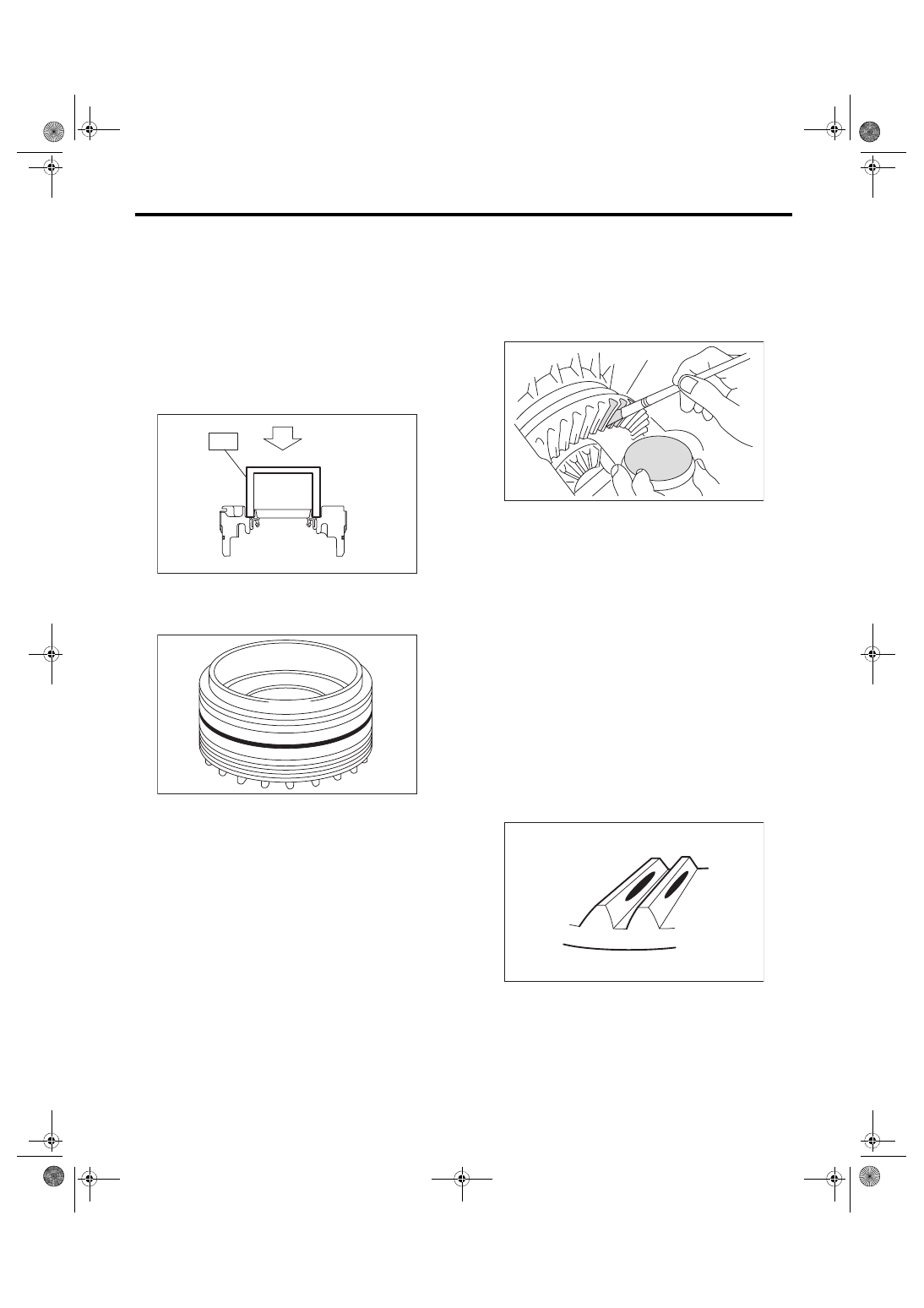
2. TOOTH CONTACT OF HYPOID GEAR
1) Check that the hypoid gear backlash is within the
standard value. Adjust if out of standard. <Ref. to
6MT-105, HYPOID GEAR BACKLASH, ADJUST-
MENT, Front Differential Assembly.>
2) Apply a thin uniform coat of lead-free red dye on
the surfaces of 3 or 4 hypoid driven gear teeth.
3) Attach the drive pinion shaft assembly, and affix
with at least 4 bolts.
NOTE:
Use old gaskets and washers to prevent the mating
surfaces of the housing from becoming damaged.
Tightening torque:
50 N·m (5.1 kgf-m, 36.9 ft-lb)
4) Turn the drive pinion shaft to the left and right for
several turns.
5) Remove the drive pinion shaft assembly, and in-
spect the mating condition of the teeth. If tooth con-
tact is not correct, perform adjustment. <Ref. to
6MT-98, ADJUSTMENT, Drive Pinion Shaft As-
• Correct tooth contact
NOTE:
In a no load condition, the tooth contact from the
center to the toe side is 50-60% (While driving, the
tooth contact will shift towards the heel side).
AT-00226
ST
AT-00219
(A) Toe side
(B) Heel side
MT-00652
(A)
(B)
MT-01401
Нет комментариевНе стесняйтесь поделиться с нами вашим ценным мнением.
Текст