Subaru Impreza 3 / Impreza WRX / Impreza WRX STI. Service manual — part 442
6MT-105
Front Differential Assembly
MANUAL TRANSMISSION AND DIFFERENTIAL
F: ADJUSTMENT
1. HYPOID GEAR BACKLASH
1) Attach the RH and LH side retainers.
ST1 18630AA010
WRENCH COMPL RETAIN-
ER (RH SIDE)
ST2 18630AA000
WRENCH ASSY (LH SIDE)
NOTE:
• Twist in the side retainer on RH side a little fur-
ther than on LH side.
• WRENCH ASSY (499787000) can also be used.
2) Attach the drive pinion shaft assembly, and affix
with 5 bolts.
NOTE:
Use old gaskets and washers to prevent the mating
surfaces of the housing from becoming damaged.
Tightening torque:
50 N·m (5.1 kgf-m, 36.9 ft-lb)
3) Using the ST, loosen the differential side retainer
RH, and twist in the differential side retainer LH un-
til the hypoid driven gear just contacts the drive pin-
ion.
ST1 18630AA010
WRENCH COMPL RETAIN-
ER (RH SIDE)
ST2 18630AA000
WRENCH ASSY (LH SIDE)
4) Use the ST to turn the drive pinion shaft a few
times.
ST 18631AA000 HANDLE
5) Repeat steps 3) and 4) until differential side re-
tainer LH does not turn anymore. For differential
side retainer RH, screw in until the inner race and
outer race just comes into contact. This is the “ze-
ro” backlash state.
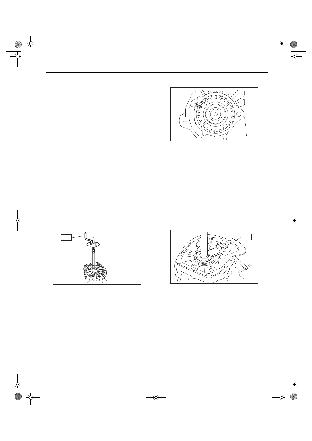
6) Mark the mating positions of the left and right
side retainers and the clutch housing.
7) Turn the back differential side retainer LH by 3
notches, and screw in the differential side retainer
RH by 3 notches.
8) Temporarily attach the LH side retainer lock
plate.
9) Turn the differential side retainer RH by 1.25
notches.
10) Temporarily attach the RH side retainer lock
plate.
NOTE:
• If the lock plate cannot be aligned, adjust the po-
sition toward the tightened side.
• The notch on the lock plate moves by 0.5 notch if
the lock plate is turned upside down when installed.
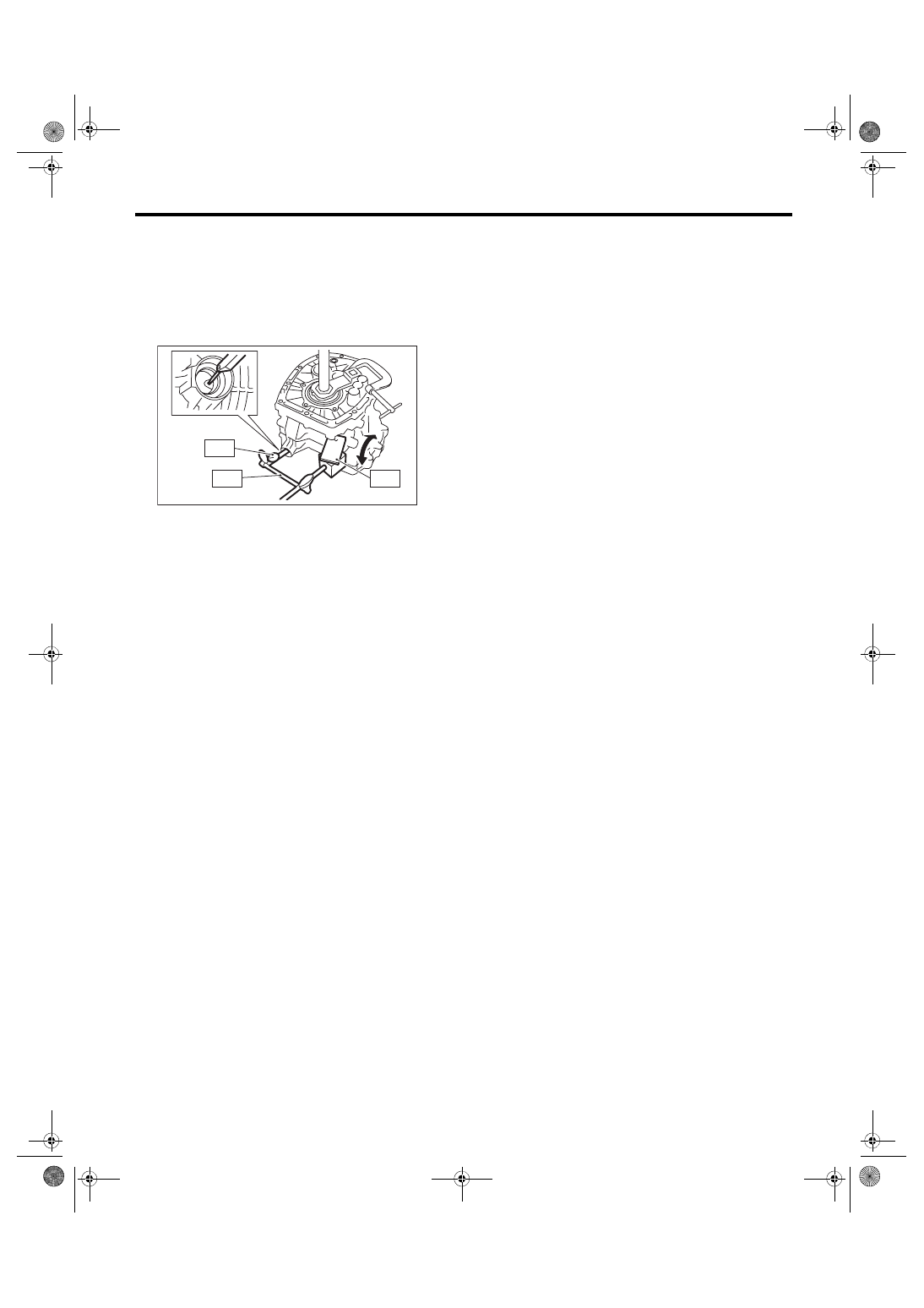
11) Use the ST to fix the drive pinion shaft in place.
ST 18621AA000 ADAPTER WRENCH
12) Install the SUBARU genuine axle shaft to the
front differential left and right sides.
Part No. 38415AA000
Axle shaft
MT-00653
ST
MT-00658
ST
MT-00674
6MT-106
Front Differential Assembly
MANUAL TRANSMISSION AND DIFFERENTIAL
13) Move the axle shaft, and measure the hypoid
gear backlash.
ST1 498255400
PLATE
ST2 498247001
MAGNET BASE
ST3 498247100
DIAL GAUGE
Hypoid gear backlash:
0.13 — 0.18 mm (0.0051 — 0.0071 in)
14) If the backlash is out of specified range, re-
move the left and right retainer lock plates and
loosen RH side differential side retainer. Then, ad-
just the LH side differential side retainer by turning
it, and attach the LH side retainer lock plate.
15) Screw in the RH side differential side retainer
until the inner race and outer race just come into
contact.
2. TOOTH CONTACT OF HYPOID GEAR
Regarding teeth contact conditions, refer to the
drive pinion section. <Ref. to 6MT-104, TOOTH
CONTACT OF HYPOID GEAR, INSPECTION,
MT-00675
ST2
ST1
ST3
6MT-107
Shifter Fork and Rod
MANUAL TRANSMISSION AND DIFFERENTIAL
22.Shifter Fork and Rod
A: REMOVAL
1) Remove the manual transmission assembly
from the vehicle. <Ref. to 6MT-31, REMOVAL,
Manual Transmission Assembly.>
2) Prepare the transmission for overhaul. <Ref. to
6MT-37, Preparation for Overhaul.>
3) Remove the neutral position switch, back-up
light switch and harness. <Ref. to 6MT-41, RE-
MOVAL, Neutral Position Switch.> <Ref. to 6MT-
39, REMOVAL, Back-up Light Switch.>
4) Remove the extension case. <Ref. to 6MT-43,
5) Remove the transfer driven gear. <Ref. to 6MT-
55, REMOVAL, Transfer Driven Gear.>
6) Remove the center differential. <Ref. to 6MT-57,
REMOVAL, Center Differential.>
7) Remove the transmission case. <Ref. to 6MT-
58, REMOVAL, Transmission Case.>
8) Remove the individual gear assemblies. <Ref. to
6MT-65, REMOVAL, Main Shaft Assembly.>
B: INSTALLATION
1) Install the individual gear assemblies all at once.
<Ref. to 6MT-66, INSTALLATION, Main Shaft As-
2) Install the transmission case. <Ref. to 6MT-60,
INSTALLATION, Transmission Case.>
3) Install the center differential. <Ref. to 6MT-57,
INSTALLATION, Center Differential.>
4) Install the transfer driven gear. <Ref. to 6MT-55,
INSTALLATION, Transfer Driven Gear.>
5) Install the extension case. <Ref. to 6MT-43, IN-
6) Install the neutral position switch, back-up light
switch and harness. <Ref. to 6MT-41, INSTALLA-
TION, Neutral Position Switch.> <Ref. to 6MT-39,
INSTALLATION, Back-up Light Switch.>
7) Install the manual transmission assembly to the
vehicle. <Ref. to 6MT-33, INSTALLATION, Manual
C: DISASSEMBLY
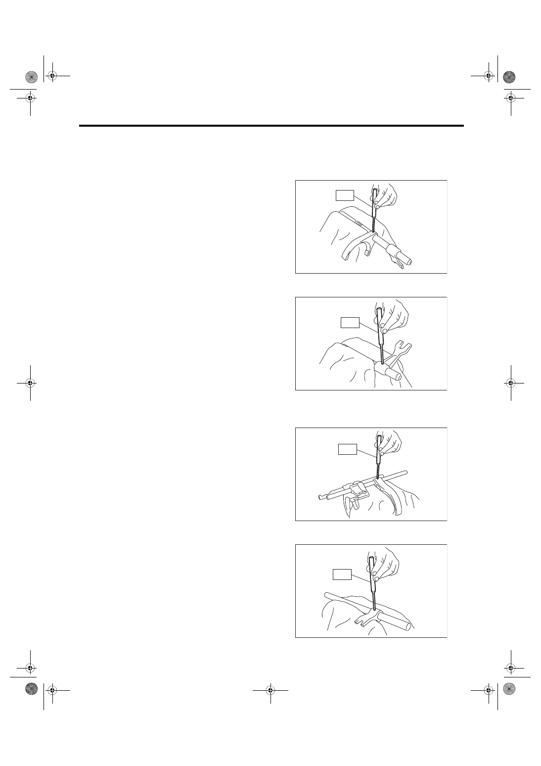
1. REVERSE SHIFTER FORK
1) Remove the reverse fork using the ST.
ST 398791700
REMOVER
2) Remove the reverse shifter arm using the ST.
ST 398791700
REMOVER
2. 1ST-2ND, 3RD-4TH SHIFTER FORK
1) Using the ST, remove the 3rd-4th shifter fork.
ST 398791700
REMOVER
2) Using the ST, remove the 3rd-4th shifter arm.
ST 398791700
REMOVER
MT-00680
ST
MT-00681
ST
MT-00682
ST
MT-00683
ST
6MT-108
Shifter Fork and Rod
MANUAL TRANSMISSION AND DIFFERENTIAL
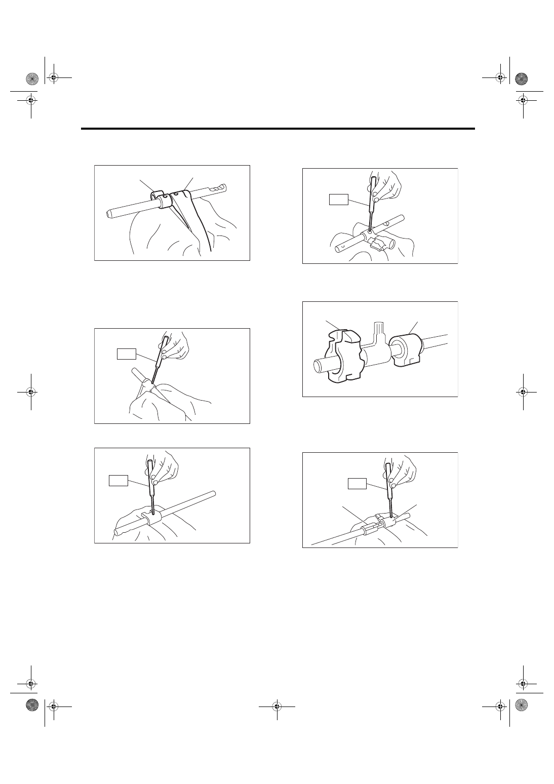
3) Using the ST, remove the 1st-2nd shifter arm
and 1st-2nd shifter fork.
ST 398791700
REMOVER
3. 5TH-6TH SHIFTER FORK
1) Using the ST, remove the 5th-6th shifter fork.
ST 398791700
REMOVER
2) Using the ST, remove the 5th-6th shifter arm.
ST 398791700
REMOVER
4. SHIFTER ARM SHAFT
Remove the selector arm using the ST.
ST 398791700
REMOVER
5. STRIKING ROD
1) Remove the reverse interlock block and the in-
terlock block from the striking rod.
2) Remove the reverse interlock arm using the ST.
ST 398791700
REMOVER
(A) 1st-2nd shifter arm
(B) 1st-2nd shifter fork
MT-00684
(A)
(B)
MT-00685
ST
MT-00686
ST
(A) Reverse interlock block
(B) Interlock block
(A) Reverse interlock arm
(B) Interlock arm
MT-01095
ST
MT-00688
(A)
(B)
MT-00689
(A)
(B)
ST
Нет комментариевНе стесняйтесь поделиться с нами вашим ценным мнением.
Текст