Subaru Impreza 3 / Impreza WRX / Impreza WRX STI. Service manual — part 401
5MT-25
Manual Transmission Assembly
MANUAL TRANSMISSION AND DIFFERENTIAL
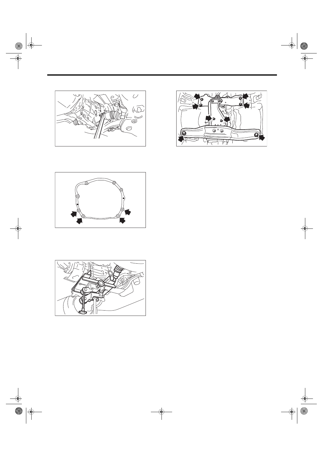
23) Using a crowbar, remove the left and right front
drive shaft from the transmission.
24) Remove the bolts and nuts which hold lower
side of transmission to engine.
25) Place the transmission jack under the transmis-
sion.
CAUTION:
Always support the transmission case with a
transmission jack.
26) Remove the front crossmember and rear cross-
member from the vehicle.
27) While lowering the transmission jack, tighten
the turnbuckle of the ST, and incline the engine unit
rearward.
28) Remove the transmission.
NOTE:
Move the transmission jack towards the rear until
the main shaft is withdrawn from the clutch disc.
29) Separate the transmission assembly from the
transmission cushion rubber.
(A) Crowbar
MT-01017
(A)
MT-00077
MT-00078
MT-01851
5MT-26
Manual Transmission Assembly
MANUAL TRANSMISSION AND DIFFERENTIAL
B: INSTALLATION
1) Replace the differential side retainer oil seal.
<Ref. to 5MT-32, REPLACEMENT, Differential
ST 18675AA000 DIFFERENTIAL SIDE OIL
SEAL INSTALLER
NOTE:
Be sure to replace the differential side retainer oil
seal after removing the front drive shaft.
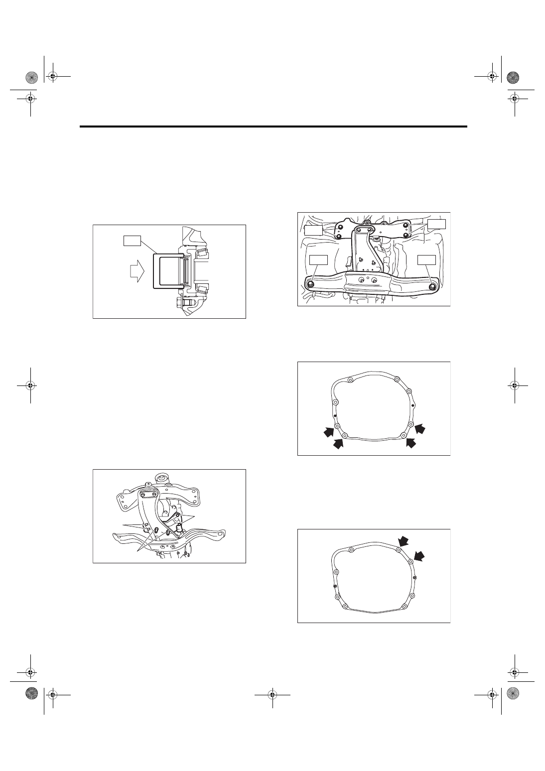
2) Tap the transmission hanger in the rear side of
transmission with a rubber hammer to bend it until
it is in close contact with the transmission case.
CAUTION:
Do not apply excessive load or impact to the
transmission case.
3) Install the transmission cushion rubber to the
transmission, and tighten the bolt (A).
4) Install the transmission cushion rubber to the
center crossmember, and tighten the nut (B).
Tightening torque:
Bolt (A)
35 N·m (3.6 kgf-m, 25.8 ft-lb)
Nut (B)
35 N·m (3.6 kgf-m, 25.8 ft-lb)
5) Install the transmission onto the engine.
(1) Lift up the transmission gradually using a
transmission jack.
(2) Engage at the spline section.
NOTE:
Be careful not to hit the main shaft against the
clutch cover.
6) While raising the transmission jack, loosen the
turnbuckle of the ST, and set the engine unit to the
original position.
7) Install the front crossmember and rear cross-
member.
Tightening torque:
T1: 70 N·m (7.1 kgf-m, 51.6 ft-lb)
T2: 140 N·m (14.3 kgf-m, 103.3 ft-lb)
8) Take out the transmission jack.
9) Tighten the bolts and nuts which hold the lower
side of transmission to the engine.
Tightening torque:
50 N·m (5.1 kgf-m, 36.9 ft-lb)
10) Connect the transmission to the engine.
(1) Install the starter. <Ref. to SC(w/o STI)-2,
(2) Tighten the bolts which hold the upper side
of the transmission to the engine.
Tightening torque:
50 N·m (5.1 kgf-m, 36.9 ft-lb)
ST
MT-00103
MT-01676
(A)
(A)
(B)
MT-01672
T 1
T 1
T 2
T 2
MT-00077
MT-01524
5MT-27
Manual Transmission Assembly
MANUAL TRANSMISSION AND DIFFERENTIAL
11) Remove the ST.
12) Install the pitching stopper.
Tightening torque:
T1: 50 N·m (5.1 kgf-m, 36.9 ft-lb)
T2: 58 N·m (5.9 kgf-m, 42.8 ft-lb)
13) Lift up the vehicle.
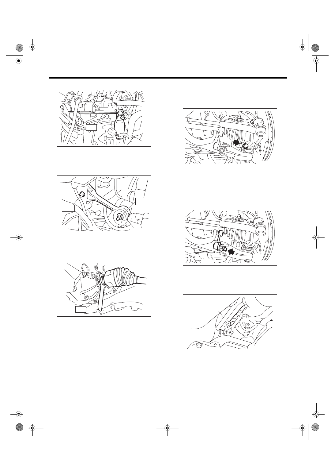
14) Install the front drive shaft into the transmis-
sion.
ST 28399SA010 OIL SEAL PROTECTOR
15) Insert the front arm ball joint into the housing
lower part, and tighten the mounting bolt.
Tightening torque:
50 N·m (5.1 kgf-m, 36.9 ft-lb)
16) Attach the stabilizer link to the front arm.
Tightening torque:
30 N·m (3.1 kgf-m, 22.1 ft-lb)
17) Attach the gear shift rod and stay.
(1) Attach the gear shift rod to the transmission.
Tightening torque:
12 N·m (1.2 kgf-m, 8.9 ft-lb)
(2) Install the stay to the transmission bracket.
Tightening torque:
18 N·m (1.8 kgf-m, 13.3 ft-lb)
MT-01226
ST
MT-00085
T2
T1
MT-02693
ST
(A) Front arm
(B) Ball joint
(A) Stay
(B) Gear shift rod
MT-01652
(B)
(A)
MT-01655
CS-00051
(A)
(B)
5MT-28
Manual Transmission Assembly
MANUAL TRANSMISSION AND DIFFERENTIAL
18) Install the propeller shaft. <Ref. to DS-12, IN-
19) Install the heat shield cover. <Ref. to EI-74, IN-
STALLATION, Heat Shield Cover.>
20) Install the hanger bracket to the transmission.
21) Install the rear exhaust pipe and muffler. <Ref.
to EX(w/o STI)-2, General Description.>
22) Install the center exhaust pipe. <Ref. to EX(w/o
23) Install the under cover. <Ref. to EI-28, INSTAL-
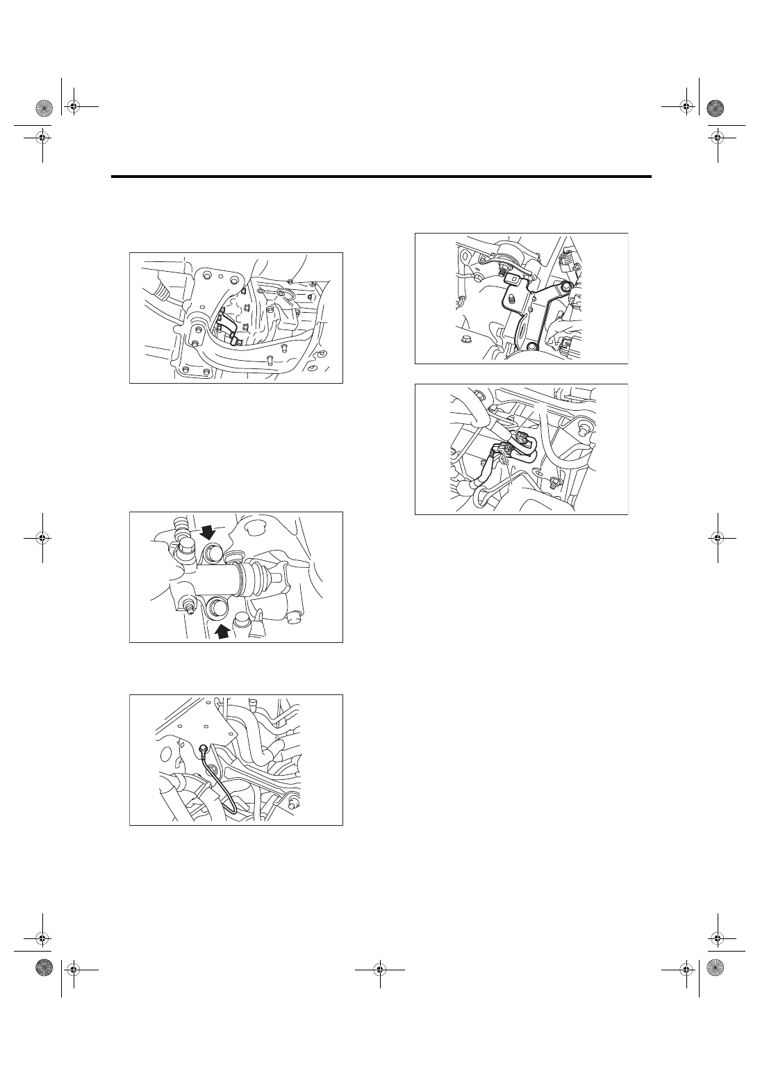
24) Install the operating cylinder.
Tightening torque:
37 N·m (3.8 kgf-m, 27.3 ft-lb)
25) Install the transmission radio ground terminal.
Tightening torque:
13 N·m (1.3 kgf-m, 9.6 ft-lb)
26) Install the engine hanger.
Tightening torque:
16 N·m (1.6 kgf-m, 11.8 ft-lb)
27) Connect the following connectors.
28) Install the intercooler. <Ref. to IN(w/o STI)-12,
29) Connect the battery ground terminal.
30) Remove the lift arm from vehicle.
MT-01653
CL-00253
MT-01650
(A) Neutral position switch and back-up light switch
connector
(B) Rear oxygen sensor connector
AT-04582
MT-01649
(B)
(A)
Нет комментариевНе стесняйтесь поделиться с нами вашим ценным мнением.
Текст