Subaru Impreza 3 / Impreza WRX / Impreza WRX STI. Service manual — part 476
RS-11
Rear Trailing Link
REAR SUSPENSION
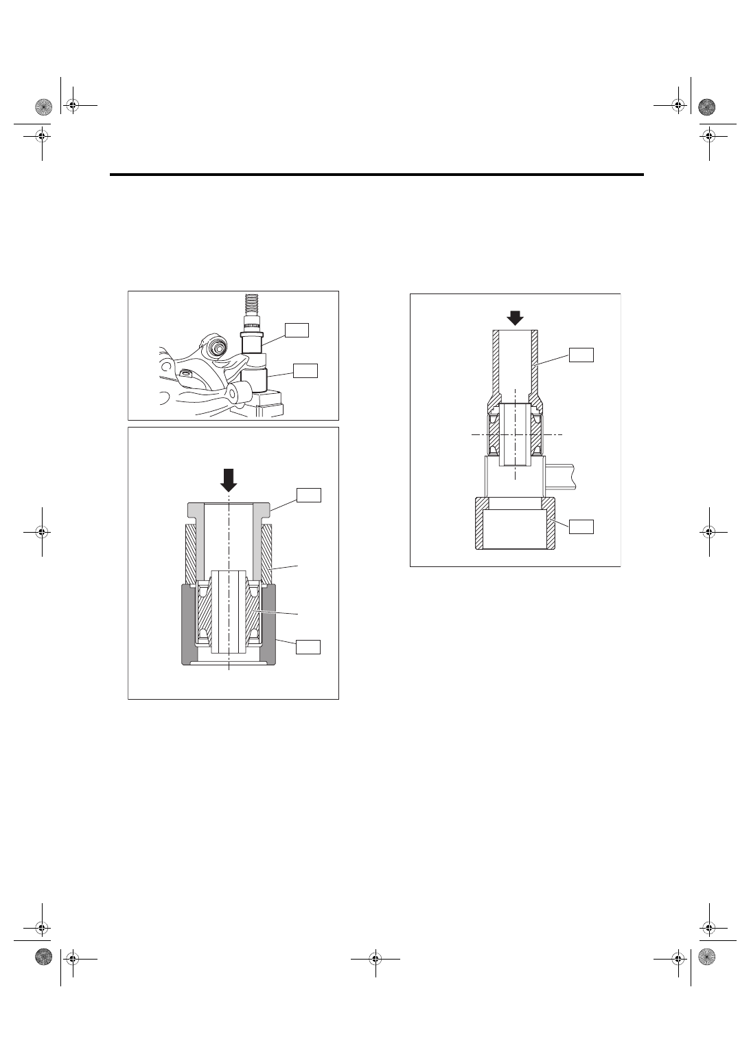
2. REAR HOUSING BUSHING
1) Remove the rear housing. <Ref. to DS-20, RE-
2) Using the ST and a hydraulic press, push out the
bushing.
ST 1 200099FG000 BUSHING REMOVER
ST 2 20099PA010
INSTALLER & REMOVER
(BASE)
D: ASSEMBLY
1. REAR TRAILING LINK BUSHING
Using the ST A and ST B, press-fit the bushing.
CAUTION:
Make sure to press the bushing straight in.
ST A 8998741000 INSTALLER
ST B 20299AG010 BASE
(1) Rear housing
(2) Bushing
DS-00458
ST1
ST2
ST1
ST2
(1)
(2)
DS-00459
ST-A
ST-B
RS-00256
RS-12
Rear Trailing Link
REAR SUSPENSION
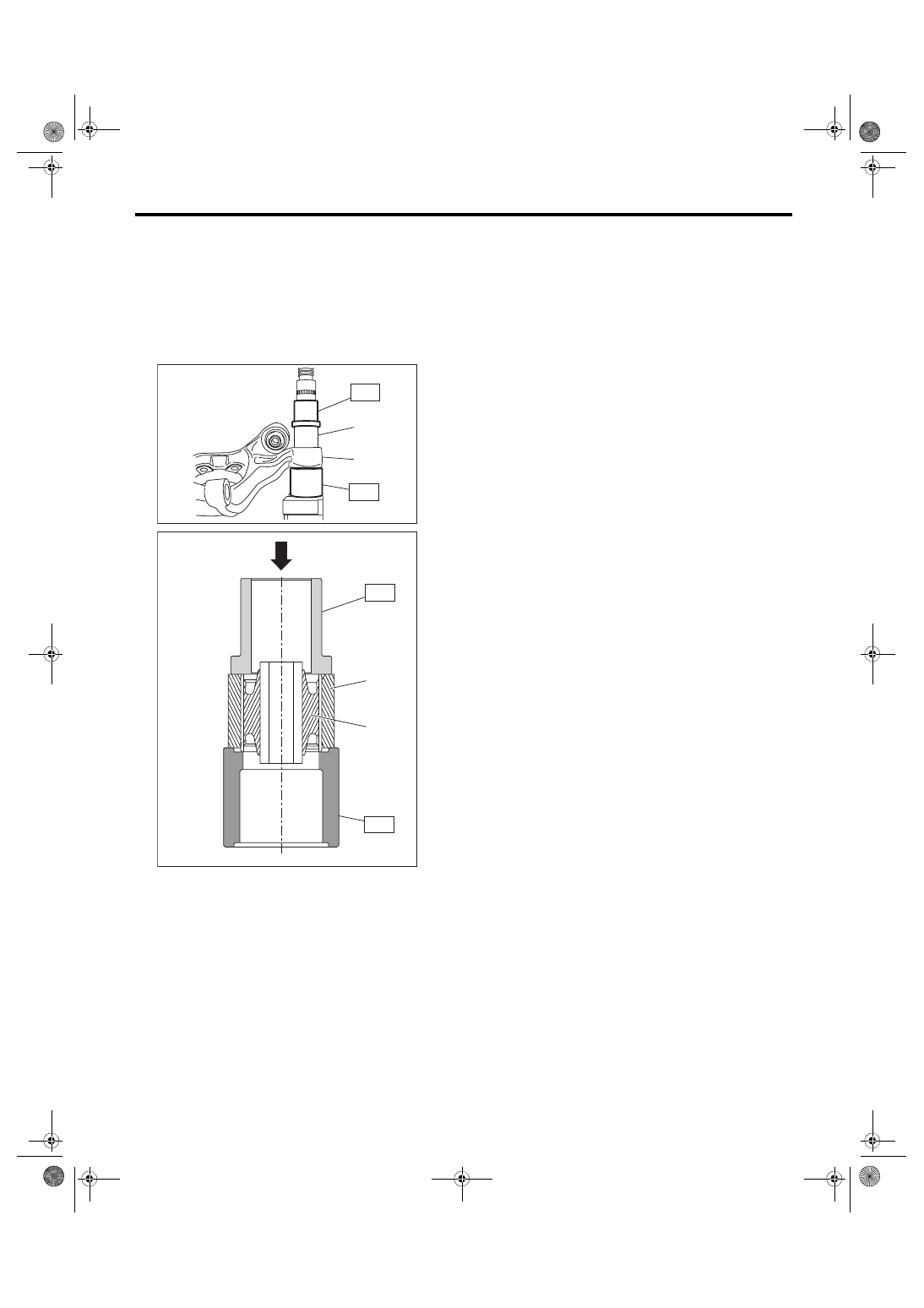
2. REAR HOUSING BUSHING
Press-fit the bushing using ST and the hydraulic
press.
CAUTION:
Make sure to press the bushing straight in.
ST 1 20099FG000 BUSHING REMOVER
ST 2 20099PA010 INSTALLER & REMOVER
(BASE)
E: INSPECTION
Perform visual check for damage or bend on the
trailing link.
(1) Rear housing
(2) Bushing
RS-00381
ST1
ST2
(2)
(1)
ST1
ST2
(1)
(2)
DS-00461
RS-13
Upper Arm
REAR SUSPENSION
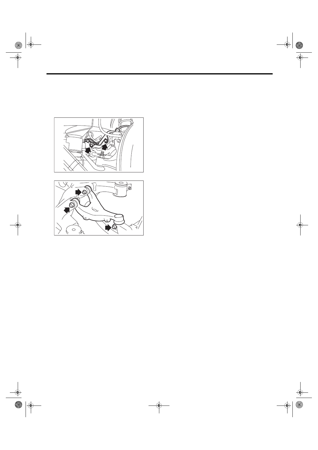
5. Upper Arm
A: REMOVAL
1) Remove the rear sub frame. <Ref. to RS-17, RE-
2) Remove the rear ABS wheel speed sensor
bracket.
3) Remove the bolts, then remove the upper arm.
B: INSTALLATION
CAUTION:
• Be sure to use a new self-locking nut.
• Always tighten the bushing when the arm is
positioned in the state where the vehicle is at
curb weight and the wheels are in full contact
with the ground.
1) Install each part in the reverse order of removal.
2) Inspect the wheel alignment and adjust if neces-
sary.
Tightening torque:
Upper arm — Rear sub frame
90 N·m (9.2 kgf-m, 66.4 ft-lb)
Upper arm — Rear housing
80 N·m (8.2 kgf-m, 59 ft-lb)
Rear ABS wheel speed sensor bracket
7.5 N·m (0.76 kgf-m, 5.5 ft-lb)
C: INSPECTION
1) Visually check the upper arm for damage and
deformation.
2) Visually check the bushing for abnormal cracks,
fatigue or damage.
RS-00257
RS-00258
RS-14
Rear Shock Absorber
REAR SUSPENSION
6. Rear Shock Absorber
A: REMOVAL
1) Remove the luggage floor mat. (5 door model)
2) Remove the strut cap of the quarter trim.
3) Remove the trunk room mat. (4 door model)
4) Lift up the vehicle, and then remove the rear
wheels.
5) Remove the nut and disconnect the rear stabiliz-
er link.
6) Remove the shock absorber lower bolt.
7) Disconnect the rear lateral link.
8) Remove the shock absorber mount nut.
9) Remove the shock absorber.
B: INSTALLATION
CAUTION:
• Be sure to use a new self-locking nut.
• Always tighten the bushing in the state where
the vehicle is at curb weight and the wheels are
in full contact with the ground.
1) Install each part in the reverse order of removal.
Tightening torque:
Refer to “COMPONENT” of “General Descrip-
tion” for the tightening torque. <Ref. to RS-3,
COMPONENT, General Description.>
2) Check the wheel alignment and adjust it if nec-
essary.
C: DISASSEMBLY
Refer to “Front Strut” for disassembly procedure.
<Ref. to FS-25, DISASSEMBLY, Front Strut.>
D: ASSEMBLY
Refer to “Front Strut” for installation procedures.
<Ref. to FS-25, ASSEMBLY, Front Strut.>
E: INSPECTION
Refer to “Front Strut” for inspection procedures.
<Ref. to FS-26, INSPECTION, Front Strut.>
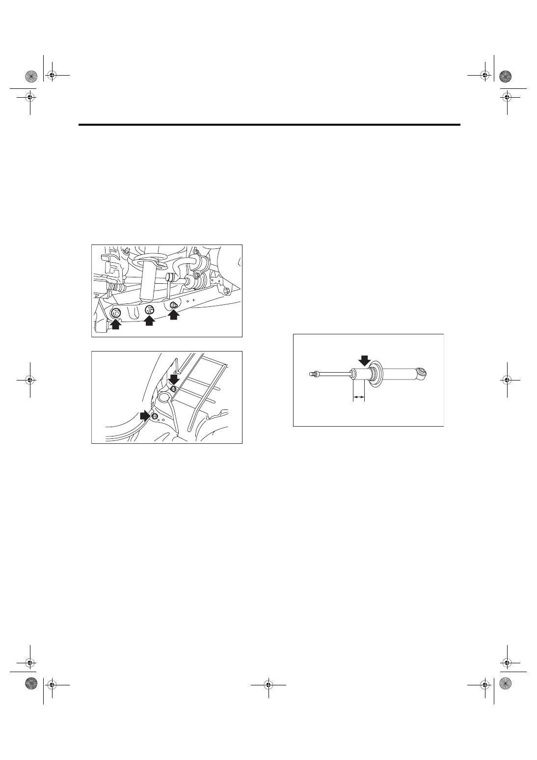
F: DISPOSAL
CAUTION:
• Before handling the shock absorber, be sure
to wear goggles to protect eyes from gas, oil
and cutting powder.
• Do not disassemble the shock absorber or
place it into a fire.
• Drill a hole into shock absorbers in case of
discarding shock absorbers filled with gas.
1) Place the shock absorber on a level surface with
the piston rod fully expanded.
2) Make a hole into the specified position 30 mm
(1.18 in) deep using a drill with 2 — 3 mm (0.08 —
0.12 in) diameter.
RS-00260
RS-00261
(1) 40 mm (1.57 in)
(1)
RS-00135
Нет комментариевНе стесняйтесь поделиться с нами вашим ценным мнением.
Текст