Subaru Impreza 3 / Impreza WRX / Impreza WRX STI. Service manual — part 241
EN(H4DOTC)(diag)-188
Diagnostic Procedure with Diagnostic Trouble Code (DTC)
ENGINE (DIAGNOSTICS)
Step
Check
Yes
No
1
CHECK OUTPUT SIGNAL OF ECM.
1) Turn the ignition switch to ON.
2) Measure the voltage between ECM connec-
tor and chassis ground.
Connector & terminal
(B134) No. 33 (+) — Chassis ground (–):
Is the voltage 10 V or more?
2
CHECK FOR POOR CONTACT.
Check for poor contact of ECM connector.
Is there poor contact of ECM
connector?
Repair the poor
contact of ECM
connector.
Even if DTC is
detected, the cir-
cuit has returned to
a normal condition
at this time. Repro-
duce the failure,
and then perform
the diagnosis
again.
NOTE:
In this case, tem-
porary open or
short circuit of har-
ness or temporary
poor contact of
connector may be
the cause.
3
CHECK POWER SUPPLY TO WASTEGATE
CONTROL SOLENOID VALVE.
Measure the voltage between wastegate con-
trol solenoid valve connector and engine
ground.
Connector & terminal
(E64) No. 1 (+) — Engine ground (–):
Is the voltage 10 V or more?
Repair the power
supply circuit.
4
CHECK HARNESS BETWEEN ECM AND
WASTEGATE CONTROL SOLENOID VALVE
CONNECTOR.
1) Turn the ignition switch to OFF.
2) Disconnect the connectors from ECM and
wastegate control solenoid valve.
3) Measure the resistance between wastegate
control solenoid valve connector and engine
ground.
Connector & terminal
(E64) No. 2 — Engine ground:
Is the resistance 1 MΩ or
more?
Repair ground
short circuit of har-
ness between
ECM connector
and wastegate
control solenoid
valve connector.
5
CHECK HARNESS BETWEEN ECM AND
WASTEGATE CONTROL SOLENOID VALVE
CONNECTOR.
Measure the resistance of harness between
ECM connector and wastegate control solenoid
valve connector.
Connector & terminal
(B134) No. 33 — (E64) No. 2:
Is the resistance less than 1 Ω? Go to step
Repair the harness
and connector.
NOTE:
In this case, repair
the following item:
• Open circuit of
harness between
ECM
connector
and
wastegate
control
solenoid
valve connector
• Poor contact of
coupling connector
EN(H4DOTC)(diag)-189
Diagnostic Procedure with Diagnostic Trouble Code (DTC)
ENGINE (DIAGNOSTICS)
6
CHECK WASTEGATE CONTROL SOLE-
NOID VALVE.
1) Remove the wastegate control solenoid
valve.
2) Measure the resistance between wastegate
control solenoid valve terminals.
Terminals
No. 1 — No. 2:
Is the resistance 10 — 100 Ω? Repair poor con-
tact of wastegate
control solenoid
valve connector.
Step
Check
Yes
No
EN(H4DOTC)(diag)-190
Diagnostic Procedure with Diagnostic Trouble Code (DTC)
ENGINE (DIAGNOSTICS)
BD:DTC P0246 TURBO/SUPER CHARGER WASTEGATE SOLENOID “A” HIGH
DTC DETECTING CONDITION:
• Immediately at fault recognition
• GENERAL DESCRIPTION <Ref. to GD(H4DOTC)-112, DTC P0246 TURBO/SUPER CHARGER
WASTEGATE SOLENOID “A” HIGH, Diagnostic Trouble Code (DTC) Detecting Criteria.>
TROUBLE SYMPTOM:
Poor driving performance
CAUTION:
After servicing or replacing faulty parts, perform Clear Memory Mode <Ref. to EN(H4DOTC)(diag)-63,
OPERATION, Clear Memory Mode.>, and Inspection Mode <Ref. to EN(H4DOTC)(diag)-49, PROCE-
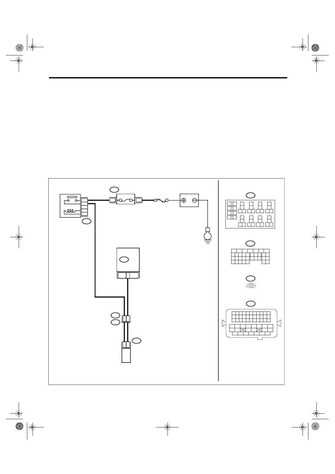
WIRING DIAGRAM:
• Engine electrical system, without SI-DRIVE <Ref. to WI-32, WITHOUT SI-DRIVE, WIRING DIAGRAM,
• Engine electrical system, with SI-DRIVE <Ref. to WI-48, WITH SI-DRIVE, WIRING DIAGRAM, Engine
ECM
EN-08729
B220
24
23
22
21
15A
B220
3
4
B134
31
30
32
29
34
33
21
20
19
18
17
16
28
27
26
15
14
13
12
11
25
23
22
24
10
3
4
9
1
2
8
7
6
5
B220
18
19
6
7
4
3
5
2
1
12
11
10
9
8
40
36 39
38
37
34
33
35
32
28 31
30
29
23
22
21
20
26
25
24
27
17
16
15
14
13
4
8
50
E2
B21
1 2
E64
B21
E64
33
B134
54
52 53
50 51
48 49
46 47
45
44
42 43
40 41
38 39
36 37
34 35
33
32
31
30
29
28
27
26
25
24
23
22
21
20
11
10
9
19
18
17
16
8
7
6
5
15
14
13
12
4
3
2
1
SBF-7
E
BATTERY
WASTEGATE CONTROL
SOLENOID VALVE
FUSE
(RELAY BLOCK)
MAIN RELAY
EN(H4DOTC)(diag)-191
Diagnostic Procedure with Diagnostic Trouble Code (DTC)
ENGINE (DIAGNOSTICS)
Step
Check
Yes
No
1
CHECK HARNESS BETWEEN ECM AND
WASTEGATE CONTROL SOLENOID VALVE
CONNECTOR.
1) Turn the ignition switch to OFF.
2) Disconnect the connectors from ECM and
wastegate control solenoid valve.
3) Turn the ignition switch to ON.
4) Measure the voltage between ECM connec-
tor and chassis ground.
Connector & terminal
(B134) No. 33 (+) — Chassis ground (–):
Is the voltage 10 V or more?
Repair short circuit
to power in har-
ness between
ECM connector
and wastegate
control solenoid
valve connector.
2
CHECK WASTEGATE CONTROL SOLE-
NOID VALVE.
1) Turn the ignition switch to OFF.
2) Measure the resistance between wastegate
control solenoid valve terminals.
Terminals
No. 1 — No. 2:
Is the resistance less than 1 Ω? Replace the
Repair the poor
contact of ECM
connector.
Нет комментариевНе стесняйтесь поделиться с нами вашим ценным мнением.
Текст