Subaru Impreza 3 / Impreza WRX / Impreza WRX STI. Service manual — part 242
EN(H4DOTC)(diag)-192
Diagnostic Procedure with Diagnostic Trouble Code (DTC)
ENGINE (DIAGNOSTICS)
BE:DTC P0300 RANDOM/MULTIPLE CYLINDER MISFIRE DETECTED
DTC DETECTING CONDITION:
• Detected when 2 consecutive driving cycles with fault occur.
• Immediately at fault recognition (A misfire which could damage catalyst occurs.)
• GENERAL DESCRIPTION <Ref. to GD(H4DOTC)-113, DTC P0300 RANDOM/MULTIPLE CYLINDER
MISFIRE DETECTED, Diagnostic Trouble Code (DTC) Detecting Criteria.>
TROUBLE SYMPTOM:
• Engine stalls.
• Improper idling
• Rough driving
CAUTION:
After servicing or replacing faulty parts, perform Clear Memory Mode <Ref. to EN(H4DOTC)(diag)-63,
OPERATION, Clear Memory Mode.>, and Inspection Mode <Ref. to EN(H4DOTC)(diag)-49, PROCE-
EN(H4DOTC)(diag)-193
Diagnostic Procedure with Diagnostic Trouble Code (DTC)
ENGINE (DIAGNOSTICS)
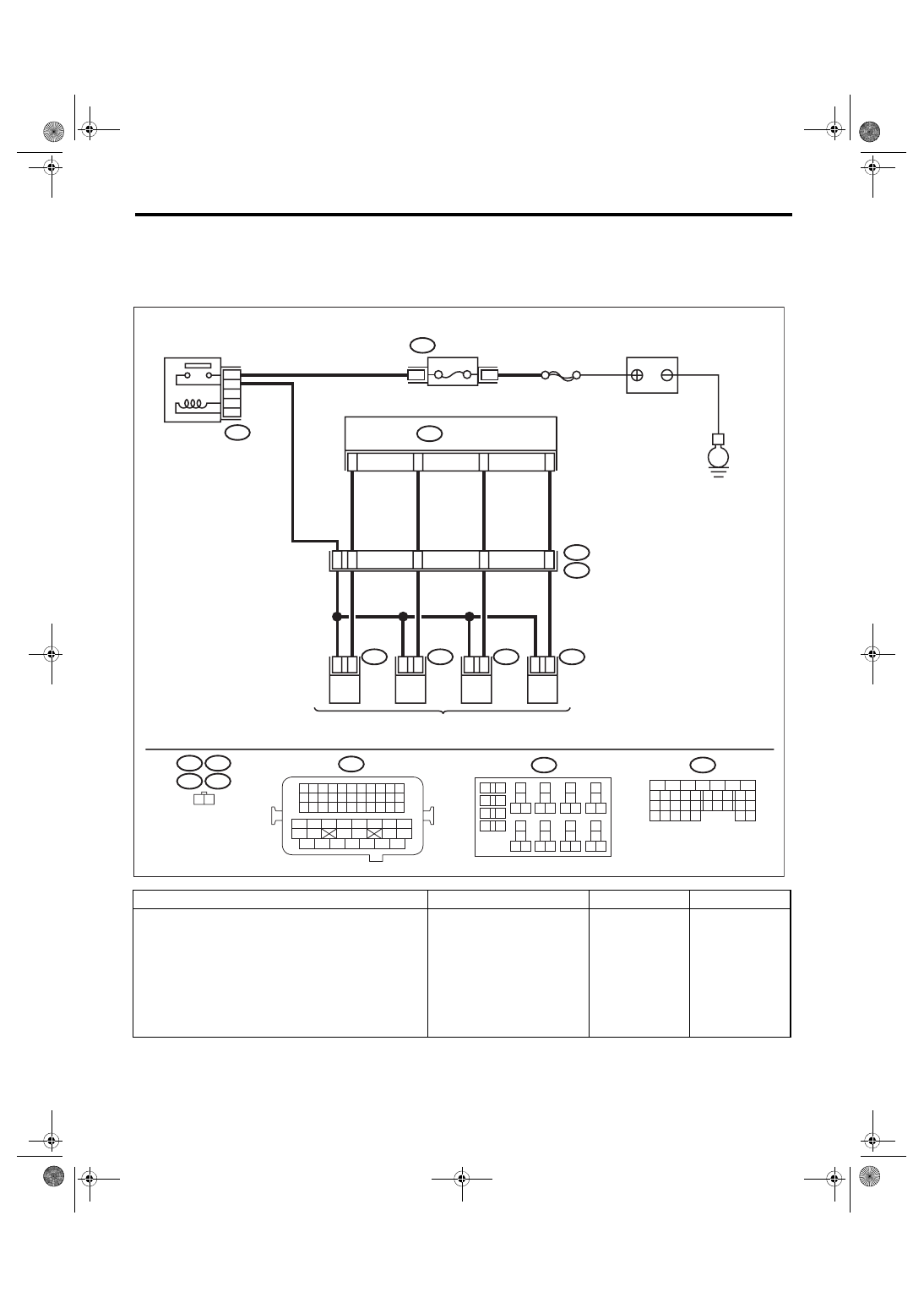
WIRING DIAGRAM:
• Engine electrical system, without SI-DRIVE <Ref. to WI-32, WITHOUT SI-DRIVE, WIRING DIAGRAM,
• Engine electrical system, with SI-DRIVE <Ref. to WI-48, WITH SI-DRIVE, WIRING DIAGRAM, Engine
Step
Check
Yes
No
1
CHECK OUTPUT SIGNAL OF ECM.
1) Turn the ignition switch to ON.
2) Measure the voltage between ECM and
chassis ground on all cylinders.
Connector & terminal
#1 (B137) No. 8 (+) — Chassis ground (–):
#2 (B137) No. 9 (+) — Chassis ground (–):
#3 (B137) No. 10 (+) — Chassis ground (–):
#4 (B137) No. 11 (+) — Chassis ground (–):
Is the voltage 10 V or more?
ECM
EN-08718
#4
2
1
#3
2
1
#2
2
1
B21
#1
2
1
4
8
54
53
52
51
10
11
12
13
1 2
B21
E5
E5
E2
E6
E6
E16
E16
E17
E17
B134
1 2 3 4
12 13 14 15
5 6 7 8
16 17 18 19
9 10 11
20 21 22
23 24 25 26 27 28 29 30 31 32 33
35
34
37
36
39
38
41
40
43
42
44 45
47
46
49
48
51
50
53
52
54
B220
24
23
22
15A
B220
3
4
21
B134
31
30
32
29
34
33
21
20
19
18
17
16
28
27
26
15
14
13
12
11
25
23
22
24
10
3
4
9
1
2
8
7
6
5
B220
18
19
6
7
4
3
5
2
1
12
11
10
9
8
40
36 39
38
37
34
33
35
32
28 31
30
29
23
22
21
20
26
25
24
27
17
16
15
14
13
E
SBF-7
MAIN RELAY
FUSE
(RELAY BLOCK)
FUEL INJECTOR
BATTERY
EN(H4DOTC)(diag)-194
Diagnostic Procedure with Diagnostic Trouble Code (DTC)
ENGINE (DIAGNOSTICS)
2
CHECK HARNESS BETWEEN ECM AND
FUEL INJECTOR CONNECTOR.
1) Turn the ignition switch to OFF.
2) Disconnect the connector from all fuel injec-
tors.
3) Measure the resistance between all fuel
injector connectors and engine ground.
Connector & terminal
#1 (E5) No. 1 — Engine ground:
#2 (E16) No. 1 — Engine ground:
#3 (E6) No. 1 — Engine ground:
#4 (E17) No. 1 — Engine ground:
Is the resistance 1 MΩ or
more?
Repair the short
circuit to ground in
harness between
ECM connector
and fuel injector
connector.
3
CHECK HARNESS BETWEEN ECM AND
FUEL INJECTOR CONNECTOR.
Measure the resistance of harness between
ECM and fuel injector connector on all cylin-
ders.
Connector & terminal
#1 (B137) No. 8 — (E5) No. 1:
#2 (B137) No. 9 — (E16) No. 1:
#3 (B137) No. 10 — (E6) No. 1:
#4 (B137) No. 11 — (E17) No. 1:
Is the resistance less than 1 Ω? Go to step
Repair the harness
and connector.
NOTE:
In this case, repair
the following item:
• Open circuit in
harness between
ECM
connector
and fuel injector
connector
• Poor contact of
coupling connector
4
CHECK FUEL INJECTOR.
Measure the resistance between all fuel injector
terminals.
Terminals
No. 1 — No. 2:
Is the resistance 5 — 20 Ω?
5
CHECK POWER SUPPLY LINE.
1) Turn the ignition switch to ON.
2) Measure the voltage between all fuel injec-
tor connectors and the engine ground.
Connector & terminal
#1 (E5) No. 2 (+) — Engine ground (–):
#2 (E16) No. 2 (+) — Engine ground (–):
#3 (E6) No. 2 (+) — Engine ground (–):
#4 (E17) No. 2 (+) — Engine ground (–):
Is the voltage 10 V or more?
Repair the poor
contact of all con-
nectors in fuel
injector circuit.
Repair the harness
and connector.
NOTE:
In this case, repair
the following item:
• Open circuit in
harness between
the main relay con-
nector and fuel in-
jector connector on
faulty cylinders
• Poor contact of
coupling connector
• Poor contact of
main relay connec-
tor
6
CHECK HARNESS BETWEEN ECM AND
FUEL INJECTOR CONNECTOR.
1) Turn the ignition switch to OFF.
2) Disconnect the connector from all fuel injec-
tors.
3) Turn the ignition switch to ON.
4) Measure the voltage between ECM and
chassis ground on all cylinders.
Connector & terminal
#1 (B137) No. 8 (+) — Chassis ground (–):
#2 (B137) No. 9 (+) — Chassis ground (–):
#3 (B137) No. 10 (+) — Chassis ground (–):
#4 (B137) No. 11 (+) — Chassis ground (–):
Is the voltage 10 V or more?
Repair the short
circuit to power in
harness between
ECM connector
and fuel injector
connectors.
Step
Check
Yes
No
EN(H4DOTC)(diag)-195
Diagnostic Procedure with Diagnostic Trouble Code (DTC)
ENGINE (DIAGNOSTICS)
7
CHECK FUEL INJECTOR.
1) Turn the ignition switch to OFF.
2) Measure the resistance between all fuel
injector terminals.
Terminals
No. 1 — No. 2:
Is the resistance 5 — 20 Ω?
8
CHECK INSTALLATION OF CAMSHAFT PO-
SITION SENSOR/CRANKSHAFT POSITION
SENSOR.
Is the camshaft position sensor
or crankshaft position sensor
loosely installed?
9
CHECK CRANK SPROCKET.
Remove the timing belt cover.
Is the crank sprocket rusted or
does it have broken teeth?
10
CHECK INSTALLATION CONDITION OF
TIMING BELT.
Turn the crankshaft, and align alignment mark
on crank sprocket with alignment mark on cylin-
der block.
ST 499987500
CRANKSHAFT
SOCKET
Is the timing belt dislocated
from its proper position?
11
CHECK FUEL LEVEL.
Is the fuel meter indication
higher than the “Lower” level?
12
CHECK STATUS OF MALFUNCTION INDI-
CATOR LIGHT.
1) Clear the memory using the Subaru Select
Monitor or general scan tool. <Ref. to
EN(H4DOTC)(diag)-63, Clear Memory Mode.>
2) Start the engine, and drive the vehicle 10
minutes or more.
Does the malfunction indicator
light illuminate or blink?
Step
Check
Yes
No
Нет комментариевНе стесняйтесь поделиться с нами вашим ценным мнением.
Текст