Subaru Impreza 3 / Impreza WRX / Impreza WRX STI. Service manual — part 240
EN(H4DOTC)(diag)-184
Diagnostic Procedure with Diagnostic Trouble Code (DTC)
ENGINE (DIAGNOSTICS)
Step
Check
Yes
No
1
CHECK POWER SUPPLY CIRCUIT TO FUEL
PUMP CONTROL UNIT.
1) Turn the ignition switch to OFF.
2) Disconnect the connector from fuel pump
control unit.
3) Turn the ignition switch to ON.
4) Measure the voltage between fuel pump
control unit connector and chassis ground.
Connector & terminal
(R122) No. 10 (+) — Chassis ground (–):
Is the voltage 10 V or more?
Repair the power
supply circuit.
NOTE:
In this case, repair
the following item:
• Open circuit or
short circuit to
ground in harness
between fuel pump
relay
connector
and fuel pump con-
trol unit connector
• Poor contact of
fuel pump relay
connector
• Poor contact of
coupling connector
2
CHECK GROUND CIRCUIT OF FUEL PUMP
CONTROL UNIT.
1) Turn the ignition switch to OFF.
2) Measure the resistance of harness between
fuel pump control unit connector and chassis
ground.
Connector & terminal
(R122) No. 5 — Chassis ground:
Is the resistance less than 5 Ω? Go to step
Repair the open
circuit in harness
between fuel pump
control unit con-
nector and chassis
ground.
3
CHECK HARNESS BETWEEN FUEL PUMP
CONTROL UNIT AND FUEL PUMP CONNEC-
TOR.
1) Disconnect the connector from fuel pump.
2) Measure the resistance of harness between
fuel pump control unit and fuel pump connector.
Connector & terminal
(R122) No. 7 — (R58) No. 5:
(R122) No. 6 — (R58) No. 6:
Is the resistance less than 1 Ω? Go to step
Repair the harness
and connector.
NOTE:
In this case, repair
the following item:
• Open circuit in
harness between
fuel pump control
unit connector and
fuel pump connec-
tor
• Poor contact of
coupling connector
4
CHECK HARNESS BETWEEN FUEL PUMP
CONTROL UNIT AND FUEL PUMP CONNEC-
TOR.
Measure the resistance between fuel pump
control unit connector and chassis ground.
Connector & terminal
(R122) No. 7 — Chassis ground:
(R122) No. 6 — Chassis ground:
Is the resistance 1 MΩ or
more?
Repair the short
circuit to ground in
harness between
fuel pump control
unit connector and
fuel pump connec-
tor.
5
CHECK HARNESS BETWEEN ECM AND
FUEL PUMP CONTROL UNIT CONNECTOR.
1) Disconnect the connector from ECM.
2) Measure the resistance of harness between
ECM connector and fuel pump control unit con-
nector.
Connector & terminal
(B135) No. 10 — (R122) No. 9:
(B136) No. 33 — (R122) No. 8:
Is the resistance less than 1 Ω? Go to step
Repair the harness
and connector.
NOTE:
In this case, repair
the following item:
• Open circuit in
harness between
ECM
connector
and fuel pump con-
trol unit connector
• Poor contact of
coupling connector
EN(H4DOTC)(diag)-185
Diagnostic Procedure with Diagnostic Trouble Code (DTC)
ENGINE (DIAGNOSTICS)
6
CHECK HARNESS BETWEEN ECM AND
FUEL PUMP CONTROL UNIT CONNECTOR.
Measure the resistance between fuel pump
control unit connector and chassis ground.
Connector & terminal
(R122) No. 9 — Chassis ground:
(R122) No. 8 — Chassis ground:
Is the resistance 1 MΩ or
more?
Repair the short
circuit to ground in
harness between
ECM connector
and fuel pump con-
trol unit connector.
7
CHECK FOR POOR CONTACT.
Check for poor contact of ECM and fuel pump
control unit connector.
Is there poor contact of ECM or
fuel pump control unit connec-
tor?
Repair the poor
contact of ECM or
fuel pump control
unit connector.
8
CHECK EXPERIENCE OF RUNNING OUT OF
FUEL.
Has the vehicle experienced
running out of fuel?
Finish the diagno-
sis.
NOTE:
DTC may be re-
corded as a result
of fuel pump idling
while running out
of fuel.
Step
Check
Yes
No
EN(H4DOTC)(diag)-186
Diagnostic Procedure with Diagnostic Trouble Code (DTC)
ENGINE (DIAGNOSTICS)
BB:DTC P0244 TURBO/SUPER CHARGER WASTEGATE SOLENOID “A”
RANGE/PERFORMANCE
DTC DETECTING CONDITION:
• Immediately at fault recognition
• GENERAL DESCRIPTION <Ref. to GD(H4DOTC)-108, DTC P0244 TURBO/SUPER CHARGER
WASTEGATE SOLENOID “A” RANGE/PERFORMANCE, Diagnostic Trouble Code (DTC) Detecting Crite-
TROUBLE SYMPTOM:
Poor driving performance
CAUTION:
After servicing or replacing faulty parts, perform Clear Memory Mode <Ref. to EN(H4DOTC)(diag)-63,
OPERATION, Clear Memory Mode.>, and Inspection Mode <Ref. to EN(H4DOTC)(diag)-49, PROCE-
Step
Check
Yes
No
1
CHECK FOR ANY OTHER DTC ON DISPLAY. Is any other DTC displayed?
2
CHECK WASTEGATE ACTUATOR PIPING
AND WASTEGATE CONTROL SOLENOID
VALVE PIPING.
Are there any damage or dis-
connection of hose in waste-
gate actuator piping or
wastegate control solenoid
valve piping?
Connect the
wastegate actuator
pipe or wastegate
control solenoid
valve pipe prop-
erly. If defective,
replace the hose.
EN(H4DOTC)(diag)-187
Diagnostic Procedure with Diagnostic Trouble Code (DTC)
ENGINE (DIAGNOSTICS)
BC:DTC P0245 TURBO/SUPER CHARGER WASTEGATE SOLENOID “A” LOW
DTC DETECTING CONDITION:
• Immediately at fault recognition
• GENERAL DESCRIPTION <Ref. to GD(H4DOTC)-110, DTC P0245 TURBO/SUPER CHARGER
WASTEGATE SOLENOID “A” LOW, Diagnostic Trouble Code (DTC) Detecting Criteria.>
TROUBLE SYMPTOM:
Poor driving performance
CAUTION:
After servicing or replacing faulty parts, perform Clear Memory Mode <Ref. to EN(H4DOTC)(diag)-63,
OPERATION, Clear Memory Mode.>, and Inspection Mode <Ref. to EN(H4DOTC)(diag)-49, PROCE-
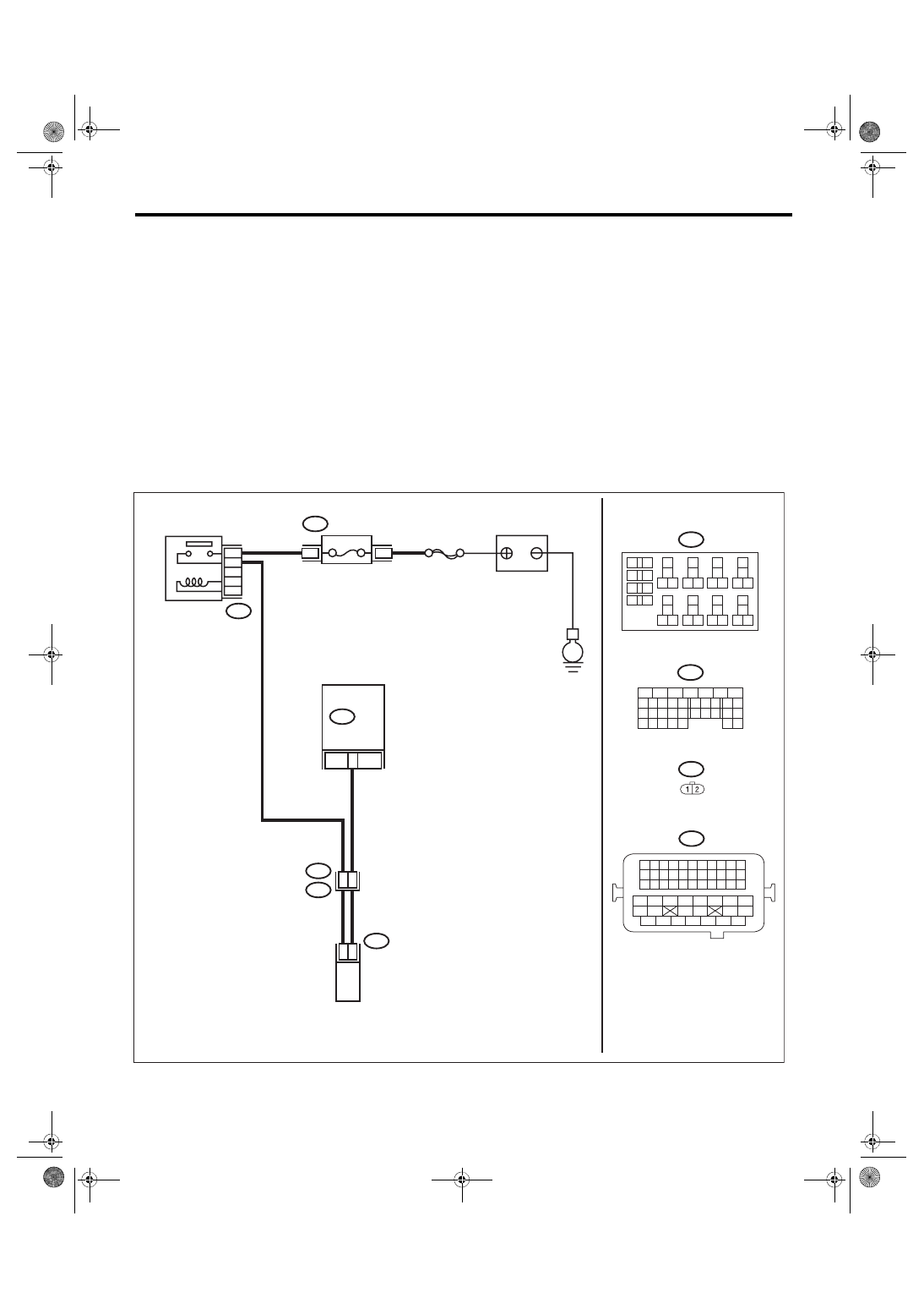
WIRING DIAGRAM:
• Engine electrical system, without SI-DRIVE <Ref. to WI-32, WITHOUT SI-DRIVE, WIRING DIAGRAM,
• Engine electrical system, with SI-DRIVE <Ref. to WI-48, WITH SI-DRIVE, WIRING DIAGRAM, Engine
ECM
EN-08729
B220
24
23
22
21
15A
B220
3
4
B134
31
30
32
29
34
33
21
20
19
18
17
16
28
27
26
15
14
13
12
11
25
23
22
24
10
3
4
9
1
2
8
7
6
5
B220
18
19
6
7
4
3
5
2
1
12
11
10
9
8
40
36 39
38
37
34
33
35
32
28 31
30
29
23
22
21
20
26
25
24
27
17
16
15
14
13
4
8
50
E2
B21
1 2
E64
B21
E64
33
B134
54
52 53
50 51
48 49
46 47
45
44
42 43
40 41
38 39
36 37
34 35
33
32
31
30
29
28
27
26
25
24
23
22
21
20
11
10
9
19
18
17
16
8
7
6
5
15
14
13
12
4
3
2
1
SBF-7
E
BATTERY
WASTEGATE CONTROL
SOLENOID VALVE
FUSE
(RELAY BLOCK)
MAIN RELAY
Нет комментариевНе стесняйтесь поделиться с нами вашим ценным мнением.
Текст