Subaru Impreza 3 / Impreza WRX / Impreza WRX STI. Service manual — part 770
IM(diag)-15
Diagnostic Procedure with Diagnostic Trouble Code (DTC)
IMMOBILIZER (DIAGNOSTICS)
10.Diagnostic Procedure with Diagnostic Trouble Code (DTC)
A: DTC B1570 ANTENNA
DTC DETECTING CONDITION:
Faulty antenna
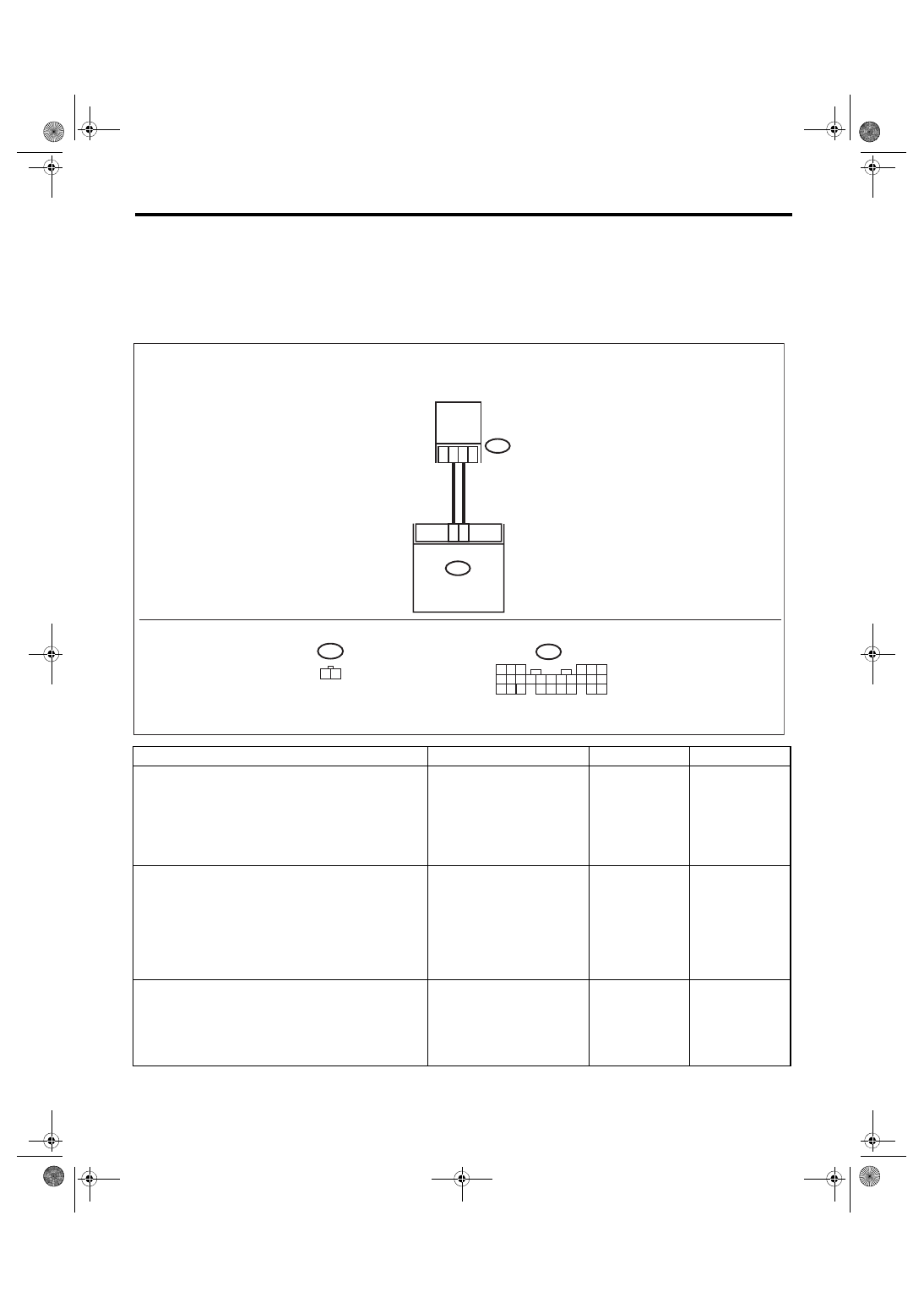
WIRING DIAGRAM:
Immobilizer system <Ref. to WI-158, WIRING DIAGRAM, Immobilizer System.>
Step
Check
Yes
No
1
CHECK ANTENNA CIRCUIT.
1) Turn the ignition switch to OFF.
2) Disconnect the connector from the antenna.
<Ref. to SL-52, Immobilizer Antenna.>
3) Measure the resistance of antenna circuit.
Connector & terminal
(B415) No. 1 — No. 2:
Is the resistance less than 6 —
10 Ω?
Replace the
antenna. <Ref. to
SL-52, Immobi-
lizer Antenna.>
2
CHECK ANTENNA CIRCUIT.
1) Disconnect the connector from body inte-
grated unit.
2) Measure the resistance between body inte-
grated unit connector and antenna connector.
Connector & terminal
(B280) No. 25 — (B415) No. 1:
(B280) No. 26 — (B415) No. 2:
Is the resistance less than 10
Ω?
Repair the har-
ness.
3
CHECK ANTENNA CIRCUIT.
Measure the resistance between body inte-
grated unit connector and chassis ground.
Connector & terminal
(B280) No. 25 — Chassis ground:
(B280) No. 26 — Chassis ground:
Is the resistance 1 MΩ or
more?
Repair the har-
ness.
B25
B26
B415
1 2
B280
B:
B415
B280
B:
IM-00279
2
1
5
4
6
7 8
2
1
9
3
10
22 23
11 12 13 14 15
24
25 26
16 17
18 19 20
1
2
ANTENNA
BODY INTEGRATED
UNIT

IM(diag)-16
Diagnostic Procedure with Diagnostic Trouble Code (DTC)
IMMOBILIZER (DIAGNOSTICS)
4
CHECK BODY INTEGRATED UNIT FUNC-
TION.
1) Connect the connector to antenna.
2) Connect the connector to body integrated
unit.
3) Insert the key into the ignition switch, then
use an oscilloscope to measure changes in volt-
age between the antenna connector and the
chassis ground.
Connector & terminal
(B280) No. 25 (+) — Chassis ground (–):
Is the maximum voltage more
than 40 V? (Approx. 0.1 second
after inserting the key) Is the
voltage 0 V? (Approx. 1 second
after inserting the key)
5
CHECK IGNITION KEY (TRANSPONDER).
1) Remove the key from ignition switch.
2) Start the engine using other key which is
already registered.
Does the engine start?
Replace the igni-
tion key (transpon-
der). Execute the
registration proce-
dure next. Refer to
the “REGISTRA-
TION MANUAL
FOR IMMOBI-
LIZER”.
Step
Check
Yes
No

IM(diag)-17
Diagnostic Procedure with Diagnostic Trouble Code (DTC)
IMMOBILIZER (DIAGNOSTICS)
B: DTC B1571 REFERENCE CODE INCOMPATIBILITY
DTC DETECTING CONDITION:
Reference code incompatibility between body integrated unit and ECM
Step
Check
Yes
No
1
PERFORM IGNITION KEY REGISTRATION.
Perform registration to all keys used for the vehi-
cle. Refer to the “REGISTRATION MANUAL
FOR IMMOBILIZER”.
Is registration of all keys com-
plete?
End.
2
CHECK FOR ANY OTHER DTC ON DISPLAY. Is any other immobilizer DTC
displayed?
IM(diag)-18
Diagnostic Procedure with Diagnostic Trouble Code (DTC)
IMMOBILIZER (DIAGNOSTICS)
C: DTC B1572 IMM CIRCUIT FAILURE (EXCEPT ANTENNA CIRCUIT)
DTC DETECTING CONDITION:
Communication failure between body integrated unit and ECM
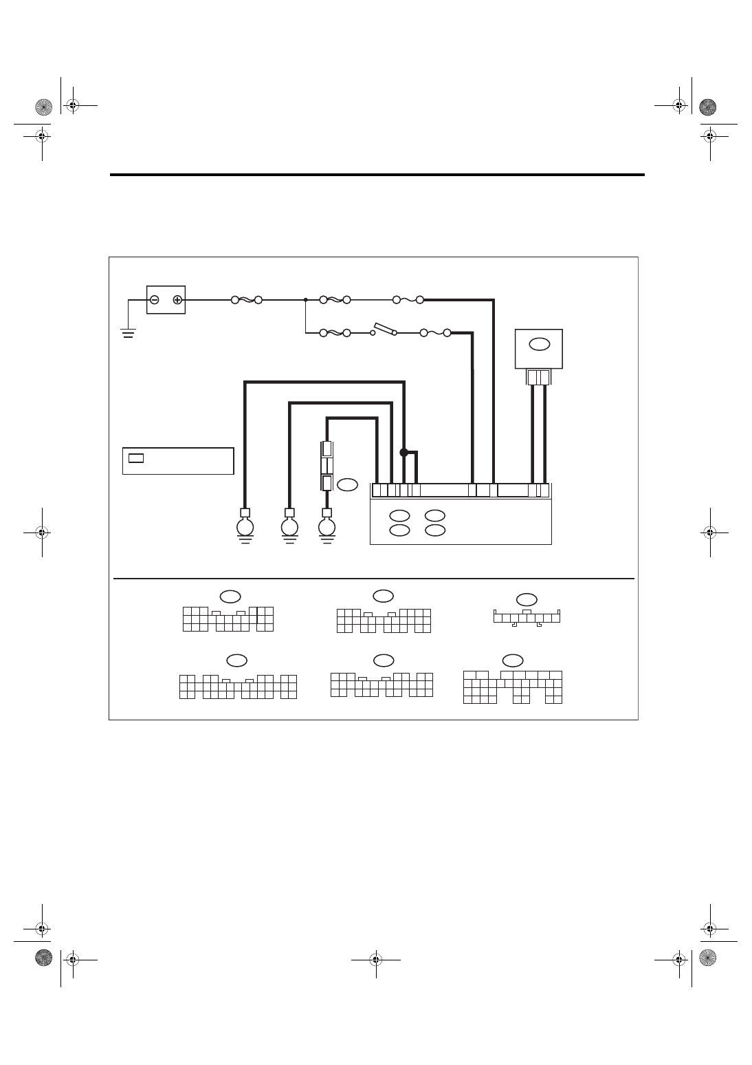
WIRING DIAGRAM:
Immobilizer system <Ref. to WI-158, WIRING DIAGRAM, Immobilizer System.>
ECM
i84
1 2
3 4
5 6
7 8
9 10 11 12 13 14 15 16 17 18 19 20 21 22 23
24 25
26 27 28 29
30 31 32 33
34 35
A:
5
4
6 7
8
2
1
9
3
10
22
23
11 12 13 14 15
24 25
26 27
16 17 18
28 29
19 20
21
30
B279
D:
B135
5
6
7
2
1
3
4
29
10 11 12 13 14 15
25
24
16
30
9
8
17 18 19
20
28
21 22 23
32
31
26 27
33
34 35
25
24
B135
B4
B15
5 6 7
8
2
1
9
4
3
10
24
22 23
25
11 12 13 14 15
26
27 28
16 17 18 19
20 21
B281
C:
5
4
6
7 8
2
1
9
3
0
1
22 23
1
1
2
1
3
1
4
1
5
1
24
25 26
6
1
7
1
8
1
9
1
0
2
1
2
B280
B:
i97
2 3 4 5
1
6 7 8
1
*
i97
1
*
1
*
B6
A2
8
D: B279
IM-00379
C: B281
B: B280
A:
i84
D27
B1
B17
C20
E
E
E
SBF-6
SBF-8
MAIN SBF
BATTERY
BODY INTEGRATED UNIT
F/B No. 7
F/B No. 12
IGNITION
SWITCH
JOINT GR
OUND
CONNECT
OR
: TERMINAL No. OPTIONAL
ARRANGEMENT
Нет комментариевНе стесняйтесь поделиться с нами вашим ценным мнением.
Текст