Subaru Impreza 3 / Impreza WRX / Impreza WRX STI. Service manual — part 769
IM(diag)-11
Diagnostics Chart for Security Indicator Light
IMMOBILIZER (DIAGNOSTICS)
8. Diagnostics Chart for Security Indicator Light
A: INSPECTION
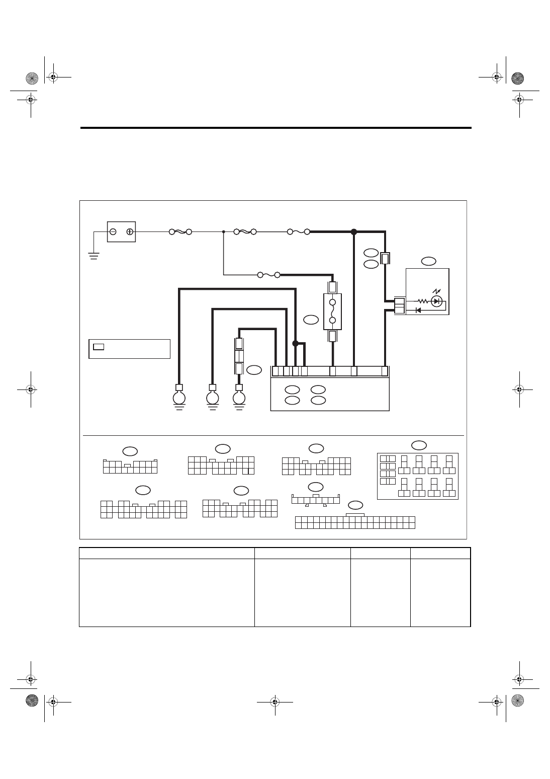
1. CHECK SECURITY INDICATOR LIGHT CIRCUIT
WIRING DIAGRAM:
Immobilizer system <Ref. to WI-158, WIRING DIAGRAM, Immobilizer System.>
Step
Check
Yes
No
1
CHECK FUSE.
1) Remove the ignition key from ignition
switch.
2) Check the fuse (M/B No. 8).
Is the fuse OK?
Replace the fuse. If
the replaced fuse
blows out easily,
repair the short cir-
cuit in the harness
between the fuse
and body inte-
grated unit.
2 3 4 5
1
6 7 8
i97
1
*
i97
1
*
1
*
B225
13
14
15 16
17
27
24
25
26
20
21
22
23
29
30
31
28
32 35
33
34
37
38
39
36
40
8
9
10
11 12
1
2
5
3
4
7
6
19
18
3
4
10A
B225
B6
i10
1 2 3 4 5 6 7 8 9 10 11 12 13 14 15 16 17 18 19 20
21 22 23 24 25 26 27 28 29 30 31 32 33 34 35 36 37 38 39 40
B: B280
5
4
6
7 8
2
1
9
3
0
1
22 23
1
1
2
1
3
1
4
1
5
1
24
25 26
6
1
7
1
8
1
9
1
0
2
1
2
A2
8
D: B279
IM-00378
16
15
14
13
12
11
10
9
8
7
6
5
4
3
2
1
i102
i102
R167
2
D:
C:
A:
B279
30
21
20
19
29
28
18
17
16
27
26
25
24
15
14
13
12
11
23
22
10
3
9
1 2
8
7
6
4 5
35
34
33
32
31
30
29
28
27
26
25
24
23
22
21
20
19
18
17
16
15
14
13
12
11
10
9
8
7
6
5
4
3
2
1
i84
B281
21
20
19
18
17
16
28
27
26
15
14
13
12
11
25
23
22
24
10
3
4
9
1 2
8
7
6
5
C: B281
B: B280
A:
i84
D27
1
39
B17
C20
C2
A10
i10
E
E
E
SBF-8
MAIN SBF
BATTERY
COMBINATION
METER
BODY INTEGRATED
UNIT
M/B No. 8
FUSE
(RELAY
BLOCK)
SECURITY/
IMMOBILIZER
INDICATOR
LIGHT
RELAY BLOCK
JOINT GR
OUND
CONNECT
OR
: TERMINAL No. OPTIONAL
ARRANGEMENT
F/B No. 7

IM(diag)-12
Diagnostics Chart for Security Indicator Light
IMMOBILIZER (DIAGNOSTICS)
2
CHECK SECURITY INDICATOR LIGHT.
1) Disconnect the connector from body inte-
grated unit.
2) Connect the resistor (100 Ω) between the
body integrated unit connector terminal (i84)
No. 10 and chassis ground.
Does the security indicator light
illuminate?
3
CHECK BODY INTEGRATED UNIT GROUND
CIRCUIT.
Measure the resistance between the body inte-
grated unit connector terminal and chassis
ground.
Connector & terminal
(i84) No. 28 — Chassis ground:
(B280) No. 17 — Chassis ground:
(B281) No. 20 — Chassis ground:
(B279) No. 27 — Chassis ground:
Is the resistance less than 10
Ω?
Repair the open
circuit of the body
integrated unit
ground circuit.
4
CHECK BODY INTEGRATED UNIT POWER
SUPPLY CIRCUIT.
Measure the voltage between the body inte-
grated unit connector terminal and chassis
ground.
Connector & terminal
(B280) No. 6 (+) — Chassis ground (–):
(B281) No. 2 (+) — Chassis ground (–):
Is the voltage 10 V or more?
Check the harness
for open or short
circuit between
body integrated
unit and fuse.
5
CHECK COMBINATION METER CIRCUIT.
1) Remove the combination meter. <Ref. to
IDI-16, Combination Meter.>
2) Measure the voltage between combination
meter connector terminal and chassis ground.
Connector & terminal
(i10) No. 1 (+) — Chassis ground (–):
Is the voltage 10 V or more?
Check for an open
or short circuit in
the harness
between the com-
bination meter and
fuse.
6
CHECK COMBINATION METER CIRCUIT.
Measure the resistance between the body inte-
grated unit connector terminal and combination
meter connector terminal.
Connector & terminal
(i84) No. 10 — (i10) No. 39:
Is the resistance less than 10
Ω?
Repair the harness
or connector.
Step
Check
Yes
No
IM(diag)-13
Diagnostics Chart for Security Indicator Light
IMMOBILIZER (DIAGNOSTICS)
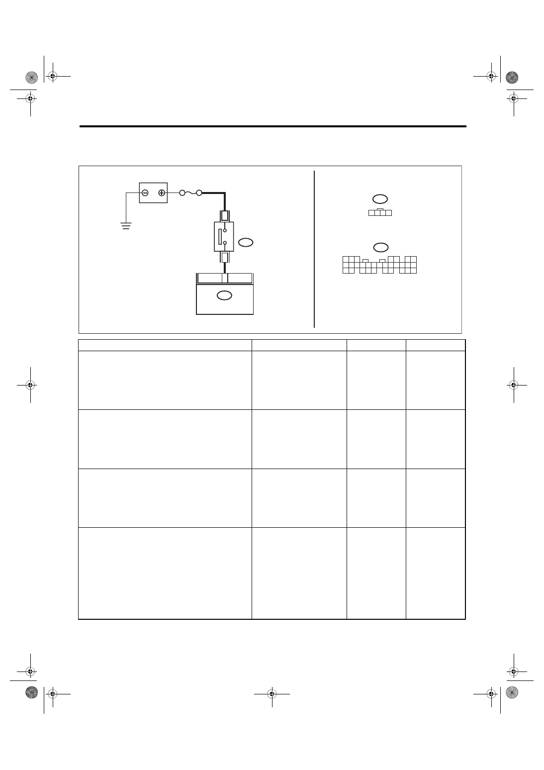
2. CHECK KEY SWITCH CIRCUIT
WIRING DIAGRAM:
Immobilizer system <Ref. to WI-158, WIRING DIAGRAM, Immobilizer System.>
Step
Check
Yes
No
1
CHECK POWER SUPPLY CIRCUIT.
1) Disconnect the connector from key warning
switch.
2) Measure the voltage between key warning
switch connector terminal and chassis ground.
Connector & terminal
(B350) No. 3 (+) — Chassis ground (–):
Is the voltage 10 V or more?
Check the harness
for an open or
short between the
key warning switch
and fuse.
2
CHECK KEY WARNING SWITCH.
1) Insert the ignition key in the ignition switch.
(OFF or ACC)
2) Measure the resistance between key warn-
ing switch connector terminals.
Connector & terminal
No. 3 — No. 4:
Is the resistance less than 1 Ω? Go to step
Replace the key
warning switch.
3
CHECK KEY WARNING SWITCH.
1) Remove the ignition key from ignition
switch.
2) Measure the resistance between key warn-
ing switch connector terminals.
Connector & terminal
No. 3 — No. 4:
Is the resistance 1 MΩ or
more?
Replace the key
warning switch.
4
CHECK HARNESS BETWEEN KEY WARN-
ING SWITCH AND BODY INTEGRATED
UNIT.
1) Disconnect the connector from body inte-
grated unit.
2) Measure the resistance between key warn-
ing switch connector terminal and body inte-
grated unit connector terminal.
Connector & terminal
(B350) No. 4 — (B279) No. 2:
Is the resistance less than 10
Ω?
Repair the harness
between key warn-
ing switch and
body integrated
unit.
IM-00278
B350
M/B No.14
D2
3
4
B350
1 2 3 4
5
4
6 7
2
9
3
10
22
23
11 12 13 14 15
24 25
26 27
16 17 18
28 29
19 20
21
30
B279
D:
B279
D:
1
8
BATTERY
KEY WARNING
SWITCH
BODY INTEGRATED
UNIT
IM(diag)-14
List of Diagnostic Trouble Code (DTC)
IMMOBILIZER (DIAGNOSTICS)
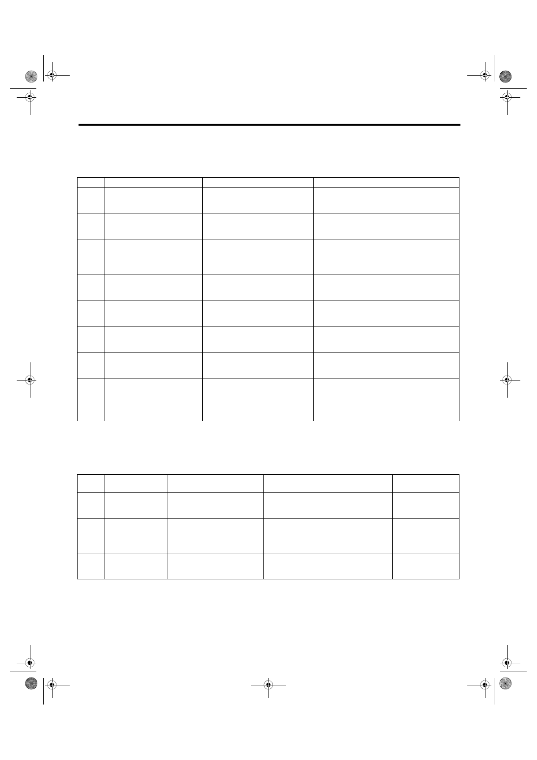
9. List of Diagnostic Trouble Code (DTC)
A: LIST
1. ECM
NOTE:
Perform diagnosis of engine DTC when a DTC other than an immobilizer DTC is detected. <Ref. to
EN(H4DOTC)(diag)-87, List of Diagnostic Trouble Code (DTC).>
2. BODY INTEGRATED UNIT
NOTE:
The starter relay control is performed in immobilizer system. When the body integrated unit detects a non-
conformity of reference code, it immediately outputs a starter relay cut signal to ECM, and then ECM stops
the starter relay operation. In this case, engine does not start, and DTC is not recorded in ECM. Check that
the engine does not start on the DTC of body integrated unit.
DTC
Item
Contents of diagnosis
Index No.
B1570 Antenna
Faulty antenna
<Ref. to IM(diag)-15, DTC B1570 ANTENNA,
Diagnostic Procedure with Diagnostic Trouble
Code (DTC).>
B1571 Reference Code Incompatibility
Reference code incompatibility
between body integrated unit and
ECM
B1572
IMM Circuit Failure
(Except Antenna Circuit)
Communication failure between
body integrated unit and ECM
B1574 Key Communication Failure
Communication failure between key
and body integrated unit
B1575 Incorrect Immobilizer Key
Incorrect immobilizer key (Use of
unregistered key in body integrated
unit)
B1576 EGI Control Module EEPROM
ECM malfunctioning
B1577 IMM Control Module EEPROM
Body integrated unit malfunctioning
B1578 Meter Failure
• Reference code incompatibility
between combination meter and
body integrated unit
• Communication failure between
body integrated unit and ECM
DTC
Item
Contents of diagnosis
Index No.
Relation between
ECM and DTC
B1401 M Collation NG
Reference code incompatibility
between combination meter
and body integrated unit
B1578
B1402
Immobilizer Key
Collation NG
• Incorrect immobilizer key
(Use of unregistered key in
body integrated unit)
• Faulty antenna
• B1575
• B1570
• B1574
B1403 E/G Request NG
Communication failure
between body integrated unit
and ECM
B1572
Нет комментариевНе стесняйтесь поделиться с нами вашим ценным мнением.
Текст