Subaru Impreza 3 / Impreza WRX / Impreza WRX STI. Service manual — part 771

IM(diag)-19
Diagnostic Procedure with Diagnostic Trouble Code (DTC)
IMMOBILIZER (DIAGNOSTICS)
Step
Check
Yes
No
1
CHECK BODY INTEGRATED UNIT POWER
SUPPLY CIRCUIT.
1) Turn the ignition switch to OFF.
2) Disconnect the connector from body inte-
grated unit.
3) Measure the voltage between the body inte-
grated unit connector terminal and chassis
ground.
Connector & terminal
(B280) No. 6 (+) — Chassis ground (–):
Is the voltage 10 V or more?
Check the harness
for open or short
circuit between
body integrated
unit and fuse.
2
CHECK BODY INTEGRATED UNIT POWER
SUPPLY CIRCUIT.
1) Turn the ignition switch to ON.
2) Measure the voltage between the body inte-
grated unit connector terminal and chassis
ground.
Connector & terminal
(B280) No. 1 (+) — Chassis ground (–):
Is the voltage 10 V or more?
Check the harness
for open or short
circuit between the
body integrated
unit and ignition
switch.
3
CHECK BODY INTEGRATED UNIT GROUND
CIRCUIT.
1) Turn the ignition switch to OFF.
2) Measure the resistance between the body
integrated unit connector terminal and chassis
ground.
Connector & terminal
(i84) No. 28 — Chassis ground:
(B280) No. 17 — Chassis ground:
(B281) No. 20 — Chassis ground:
(B279) No. 27 — Chassis ground:
Is the resistance less than 10
Ω?
Repair the open
circuit of the body
integrated unit
ground circuit.
4
CHECK GROUND CIRCUIT FOR ECM.
Measure the resistance between the ECM
ground terminal and engine ground.
Is the resistance less than 10
Ω?
Repair the ECM
ground circuit.
5
CHECK HARNESS BETWEEN BODY INTE-
GRATED UNIT AND ECM.
1) Disconnect the connector from the ECM
and body integrated unit.
2) Measure the resistance between body inte-
grated unit connector terminal and ECM con-
nector terminal.
Connector & terminal
(B280) No. 4 — (B135) No. 25:
(B280) No. 15 — (B135) No. 24:
Is the resistance less than 10
Ω?
Repair the open
circuit of the har-
ness between the
body integrated
unit and ECM.
6
CHECK COMMUNICATION CIRCUIT HAR-
NESS.
1) Turn the ignition switch to ON.
2) Measure the voltage between the body inte-
grated unit connector terminal and chassis
ground.
Connector & terminal
(B280) No. 4 (+) — Chassis ground (–):
(B280) No. 15 (+) — Chassis ground (–):
Is the voltage 6 V or more?
Repair the harness
between body inte-
grated unit and
ECM.
7
CHECK COMMUNICATION CIRCUIT HAR-
NESS.
Measure the voltage between ECM connector
terminal and engine ground.
Connector & terminal
(B135) No. 24 (+) — Engine ground (–):
(B135) No. 25 (+) — Engine ground (–):
Is the voltage 6 V or more?
Repair the harness
between body inte-
grated unit and
ECM.
IM(diag)-20
Diagnostic Procedure with Diagnostic Trouble Code (DTC)
IMMOBILIZER (DIAGNOSTICS)
NOTE:
B1578 METER FAILURE, Diagnostic Procedure with Diagnostic Trouble Code (DTC).>
8
CHECK ECM BY COMMUNICATION SHORT
CHECK.
1) Connect the connector to ECM.
2) Disconnect the connector from body inte-
grated unit.
3) Start the communication short check. <Ref.
to IM(diag)-8, COMMUNICATION LINE
CHECK, OPERATION, Subaru Select Moni-
tor.>
Is the communication short
check OK?
Step
Check
Yes
No
IM(diag)-21
Diagnostic Procedure with Diagnostic Trouble Code (DTC)
IMMOBILIZER (DIAGNOSTICS)
D: DTC B1574 KEY COMMUNICATION FAILURE
DTC DETECTING CONDITION:
Communication failure between key and body integrated unit
WIRING DIAGRAM:
Immobilizer system <Ref. to WI-158, WIRING DIAGRAM, Immobilizer System.>
Step
Check
Yes
No
1
CHECK BODY INTEGRATED UNIT FUNC-
TION.
Insert the key into the ignition switch (LOCK
position), then measure changes in voltage
between the antenna connector and the chas-
sis ground.
Connector & terminal
(B415) No. 1 (+) — Chassis ground (–):
Is the maximum voltage more
than 40 V? (Approx. 0.1 second
after inserting the key) Is the
voltage 0 V? (Approx. 1 second
after inserting the key)
2
CHECK IGNITION KEY (TRANSPONDER).
1) Remove the key from ignition switch.
2) Start the engine using other key which is
already registered.
Does the engine start?
Register ignition
keys (transpon-
ders). Refer to the
“REGISTRATION
MANUAL FOR
IMMOBILIZER”.
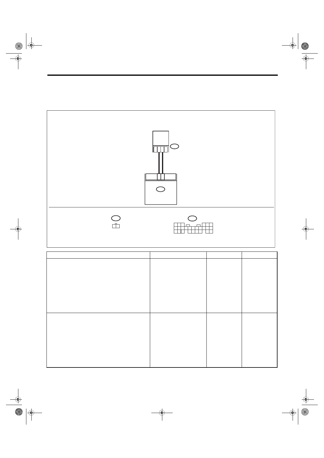
B25
B26
B415
1 2
B280
B:
B415
B280
B:
IM-00279
2
1
5
4
6
7 8
2
1
9
3
10
22 23
11 12 13 14 15
24
25 26
16 17
18 19 20
1
2
ANTENNA
BODY INTEGRATED
UNIT

IM(diag)-22
Diagnostic Procedure with Diagnostic Trouble Code (DTC)
IMMOBILIZER (DIAGNOSTICS)
E: DTC B1575 INCORRECT IMMOBILIZER KEY
DTC DETECTING CONDITION:
Incorrect immobilizer key (use of unregistered key in body integrated unit)
Step
Check
Yes
No
1
PERFORM IGNITION KEY REGISTRATION.
Perform registration to all keys used for the vehi-
cle. Refer to the “REGISTRATION MANUAL
FOR IMMOBILIZER”.
Is registration of all keys com-
plete?
End.
Replace ignition
keys (including
transponder)
which cannot be
registered. Go to
step
2
PERFORM IGNITION KEY REGISTRATION.
Perform registration to all keys used for the vehi-
cle. Refer to the “REGISTRATION MANUAL
FOR IMMOBILIZER”.
Is registration of all keys com-
plete?
End.
Нет комментариевНе стесняйтесь поделиться с нами вашим ценным мнением.
Текст