Subaru Impreza 3 / Impreza WRX / Impreza WRX STI. Service manual — part 269
EN(H4DOTC)(diag)-300
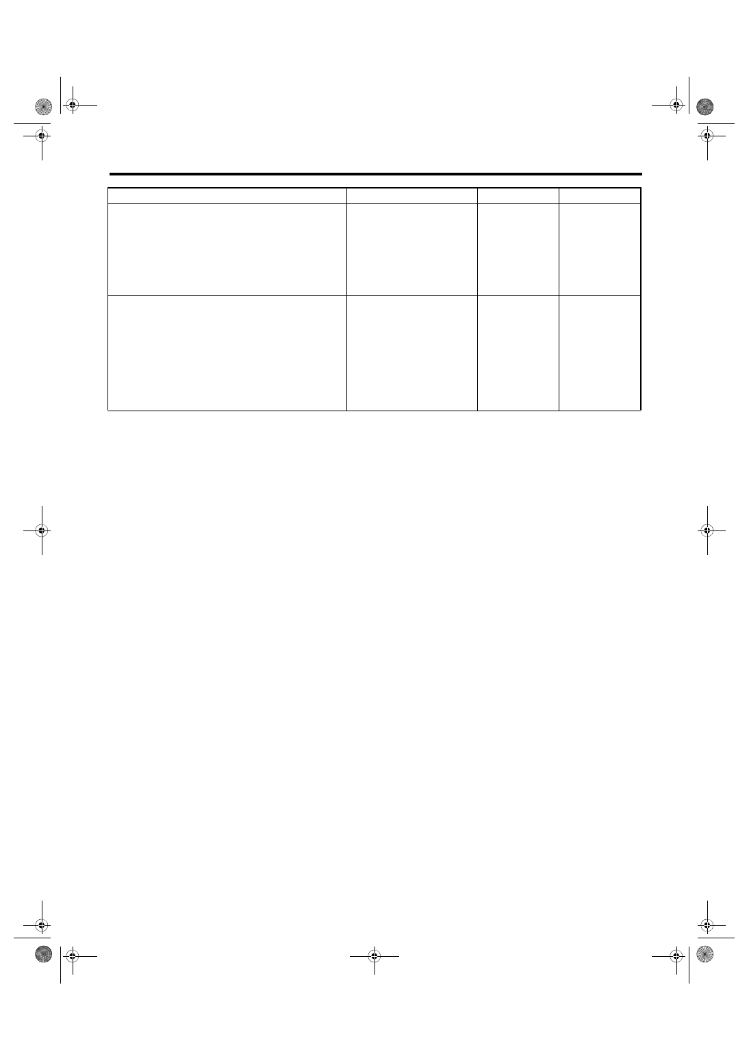
Diagnostic Procedure with Diagnostic Trouble Code (DTC)
ENGINE (DIAGNOSTICS)
Step
Check
Yes
No
1
CHECK INPUT SIGNAL OF ECM.
1) Turn the ignition switch to ON.
2) Place the shift lever in a position other than
neutral.
3) Measure the voltage between ECM connec-
tor and chassis ground.
Connector & terminal
(B136) No. 35 (+) — Chassis ground (–):
Is the voltage 10 V or more?
Repair the poor
contact of ECM
connector.
2
CHECK HARNESS BETWEEN ECM AND
NEUTRAL POSITION SWITCH CONNEC-
TOR.
1) Turn the ignition switch to OFF.
2) Disconnect the connectors from ECM and
neutral position switch.
3) Measure the resistance between ECM con-
nector and chassis ground.
Connector & terminal
(B136) No. 35 — Chassis ground:
Is the resistance 1 MΩ or
more?
Repair the short
circuit to ground
harness between
ECM connector
and neutral posi-
tion switch connec-
tor.
EN(H4DOTC)(diag)-301
Diagnostic Procedure with Diagnostic Trouble Code (DTC)
ENGINE (DIAGNOSTICS)
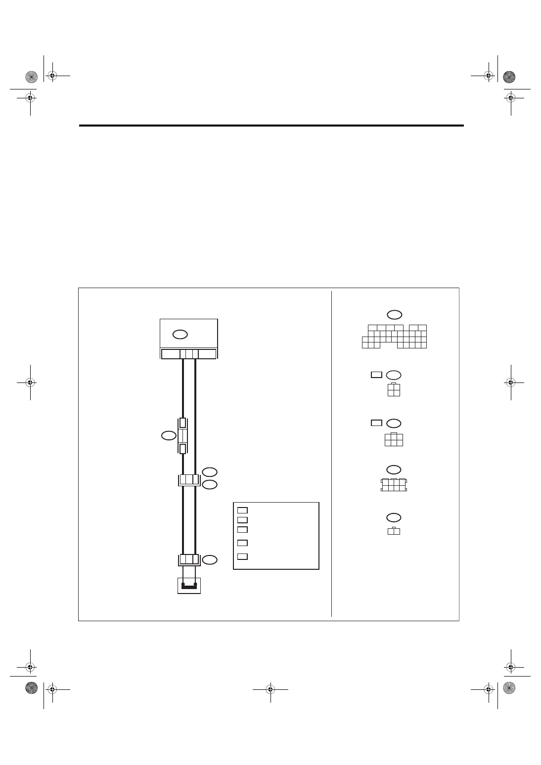
DJ:DTC P0852 NEUTRAL SWITCH INPUT CIRCUIT HIGH (MT MODEL)
DTC DETECTING CONDITION:
• Detected when 2 consecutive driving cycles with fault occur.
• GENERAL DESCRIPTION <Ref. to GD(H4DOTC)-204, DTC P0852 NEUTRAL SWITCH INPUT CIRCUIT
HIGH (MT MODEL), Diagnostic Trouble Code (DTC) Detecting Criteria.>
TROUBLE SYMPTOM:
Improper idling
CAUTION:
After servicing or replacing faulty parts, perform Clear Memory Mode <Ref. to EN(H4DOTC)(diag)-63,
OPERATION, Clear Memory Mode.>, and Inspection Mode <Ref. to EN(H4DOTC)(diag)-49, PROCE-
WIRING DIAGRAM:
• Engine electrical system, without SI-DRIVE <Ref. to WI-32, WITHOUT SI-DRIVE, WIRING DIAGRAM,
• Engine electrical system, with SI-DRIVE <Ref. to WI-48, WITH SI-DRIVE, WIRING DIAGRAM, Engine
EN-08739
35
B128
B128
T9
*
3
B136
B122
4
T12
B122
*
3
*
2
*
1
5M
6M
*
1
*
1
T12
1
2
B136
*
2
B128
3 4
1 2
6M
5M
2
6
5
4
3
1
2
1
35
31
30
32
29
34
33
21
20
19
18
17
16
28
27
26
15
14
13
12
11
25
23
22
24
10
3
4
9
1
2
8
7
6
5
8
7
6
5
4
3
2
1
:
:
ECM
: 5MT MODEL
: 6MT MODEL
: TERMINAL No.
OPTIONAL ARRANGEMENT
: 5MT MODEL : 1
6MT MODEL : 2
: 5MT MODEL : 3
6MT MODEL : 5
NEUTRAL
POSITION
SWITCH
EN(H4DOTC)(diag)-302
Diagnostic Procedure with Diagnostic Trouble Code (DTC)
ENGINE (DIAGNOSTICS)
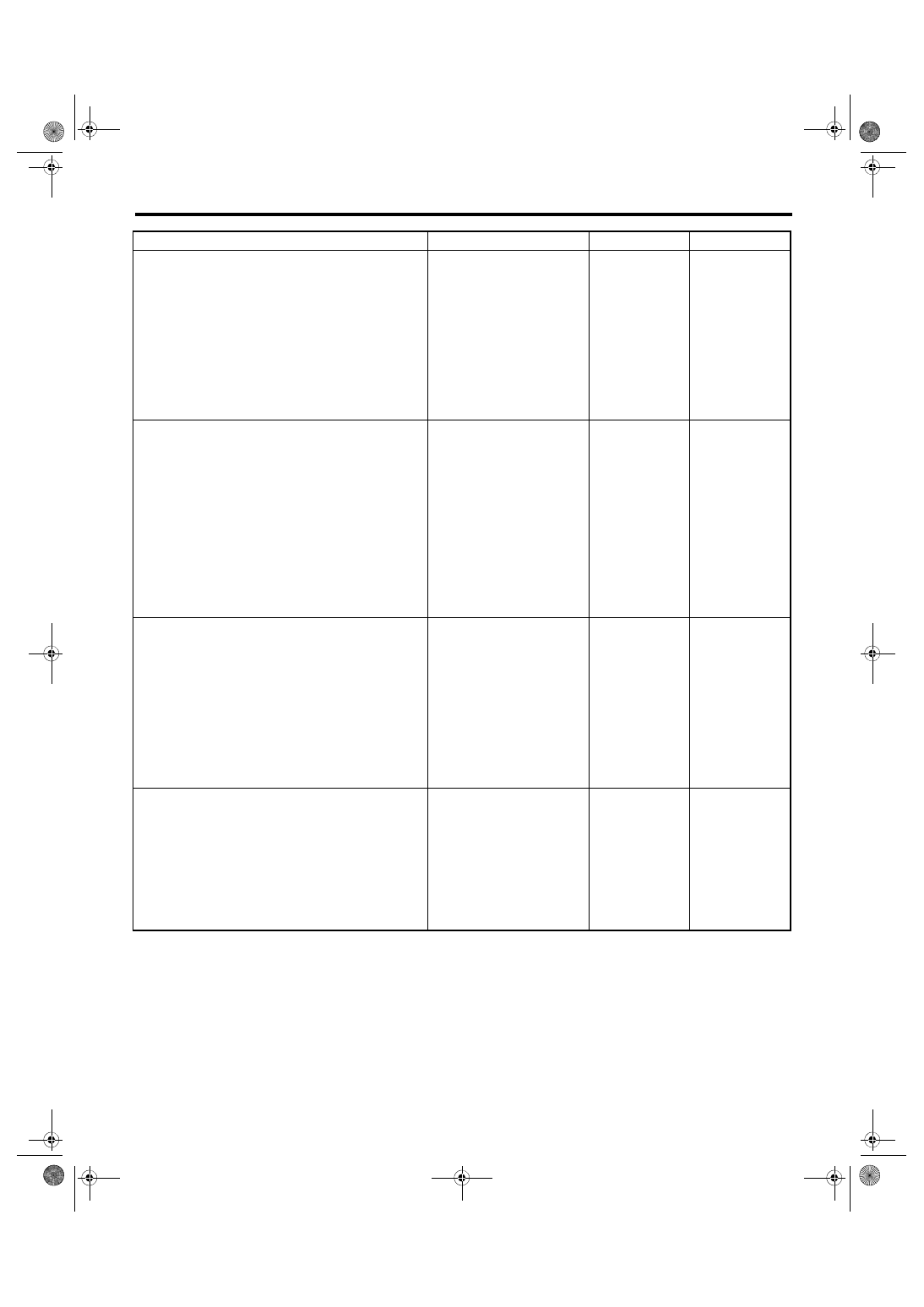
DK:DTC P1160 RETURN SPRING FAILURE
NOTE:
For the diagnostic procedure, refer to DTC P2101. <Ref. to EN(H4DOTC)(diag)-371, DTC P2101 THROT-
TLE ACTUATOR CONTROL MOTOR CIRCUIT RANGE/PERFORMANCE, Diagnostic Procedure with Di-
Step
Check
Yes
No
1
CHECK INPUT SIGNAL OF ECM.
1) Turn the ignition switch to ON.
2) Place the shift lever in neutral.
3) Measure the voltage between ECM connec-
tor and chassis ground.
Connector & terminal
(B136) No. 35 (+) — Chassis ground (–):
Is the voltage less than 1 V?
2
CHECK HARNESS BETWEEN ECM AND
NEUTRAL POSITION SWITCH CONNEC-
TOR.
1) Turn the ignition switch to OFF.
2) Disconnect the connectors from ECM and
transmission harness connector (T9).
3) Measure the resistance of harness between
ECM connector and transmission harness con-
nector.
Connector & terminal
5MT model
(B136) No. 35 — (B128) No. 1:
6MT model
(B136) No. 35 — (B128) No. 2:
Is the resistance less than 1 Ω? Go to step
Repair the open
circuit in harness
between ECM con-
nector and trans-
mission harness
connector.
3
CHECK HARNESS BETWEEN ECM AND
NEUTRAL POSITION SWITCH CONNEC-
TOR.
Measure the resistance of harness between
ECM connector and transmission harness con-
nector.
Connector & terminal
5MT model
(B128) No. 3 — (B136) No. 4:
6MT model
(B128) No. 5 — (B136) No. 4:
Is the resistance less than 5 Ω? Go to step
Repair the harness
and connector.
NOTE:
In this case, repair
the following item:
• Open circuit in
harness between
ECM
connector
and transmission
harness connector
• Poor contact of
coupling connector
4
CHECK NEUTRAL POSITION SWITCH.
1) Place the shift lever in neutral.
2) Measure the resistance between transmis-
sion harness connector terminals.
Connector & terminal
5MT model
(T9) No. 1 — No. 3:
6MT model
(T9) No. 2 — No. 5:
Is the resistance less than 1 Ω? Repair the poor
contact of trans-
mission harness
connector.
EN(H4DOTC)(diag)-303
Diagnostic Procedure with Diagnostic Trouble Code (DTC)
ENGINE (DIAGNOSTICS)
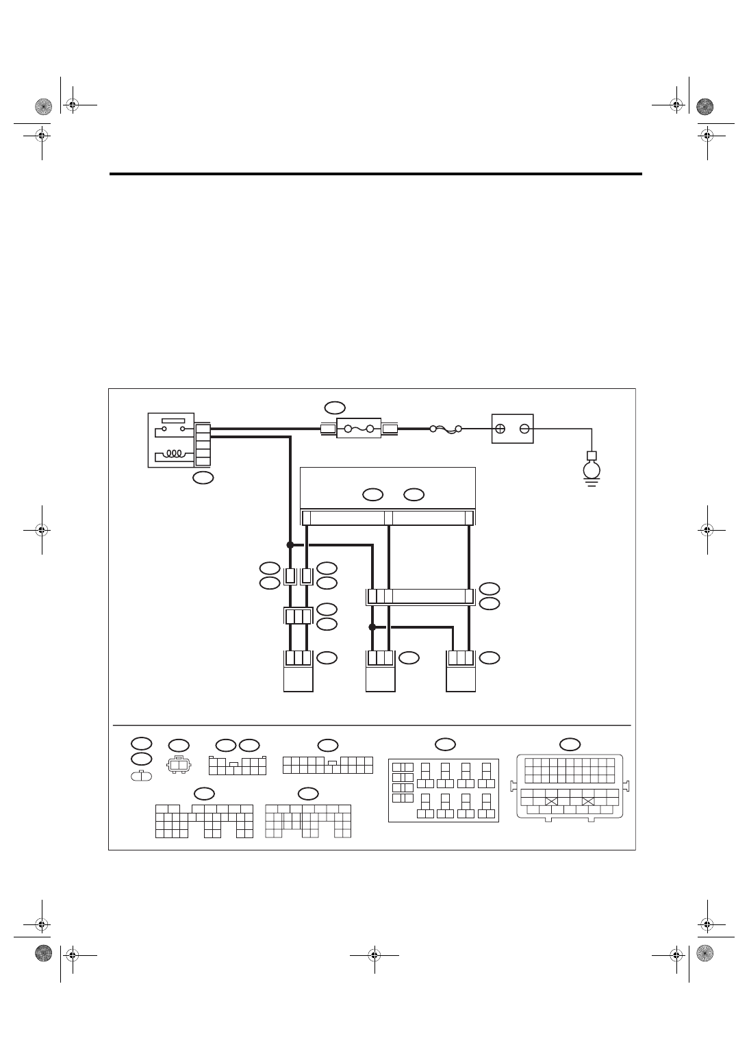
DL:DTC P1400 FUEL TANK PRESSURE CONTROL SOLENOID VALVE CIRCUIT
LOW
DTC DETECTING CONDITION:
• Detected when 2 consecutive driving cycles with fault occur.
• GENERAL DESCRIPTION <Ref. to GD(H4DOTC)-207, DTC P1400 FUEL TANK PRESSURE CONTROL
SOLENOID VALVE CIRCUIT LOW, Diagnostic Trouble Code (DTC) Detecting Criteria.>
CAUTION:
After servicing or replacing faulty parts, perform Clear Memory Mode <Ref. to EN(H4DOTC)(diag)-63,
OPERATION, Clear Memory Mode.>, and Inspection Mode <Ref. to EN(H4DOTC)(diag)-49, PROCE-
WIRING DIAGRAM:
• Engine electrical system, without SI-DRIVE <Ref. to WI-32, WITHOUT SI-DRIVE, WIRING DIAGRAM,
• Engine electrical system, with SI-DRIVE <Ref. to WI-48, WITH SI-DRIVE, WIRING DIAGRAM, Engine
ECM
5
6
7
8
2
1
9
4
3
10
24
22 23
25
11 12 13 14 15
26 27
28
16 17 18 19
20 21
29 30 31
32 33
34 35
B135
B:
5
6
7
8
2
1
9
4
3
10
22 23
11 12 13 14 15
24 25
26
16 17
18 19 20 21
27
28 29
30 31
B137
D:
B21
1 2 3 4 5 6 7 8 9 10 11
12 13 14 15 16 17 18 19 20 21 22
23 24 25 26 27 28 29 30 31 32 33
34 35
42 43
36 37 38 39
48 49 50 51 52 53 54
40 41
44 45
46 47
E52
E4
1 2
B3
D15
D6
E2
B21
44
11
4
8
E4
2
1
E52
2
1
R68
2
1
B135
B:
R57
R15
10
11
R1
B97
R2
B98
7
10
R68
1 2
B220
13
14
15 16
17
27
24
25
26
20
21
22
23
29
30
31
28
32 35
33
34
37
38
39
36
40
8
9
10
11 12
1
2
5
3
4
7
6
19
18
R57
B97
1 2
3 4 5
6 7 8 9 10 11 12
EN-09251
B98
2 3 4 5
6 7 8 9
11 12 13 14
17 18 19 20
1
10
15 16
B220
24
23
22
21
B220
4
3
B137
D:
SBF-7
E
FUSE
(RELAY BLOCK)
MAIN RELAY
BATTERY
PRESSURE CONTROL
SOLENOID VALVE ASSY
PURGE CONTROL
SOLENOID VALVE 2
PURGE CONTROL
SOLENOID VALVE 1
Нет комментариевНе стесняйтесь поделиться с нами вашим ценным мнением.
Текст