Subaru Impreza 3 / Impreza WRX / Impreza WRX STI. Service manual — part 267
EN(H4DOTC)(diag)-292
Diagnostic Procedure with Diagnostic Trouble Code (DTC)
ENGINE (DIAGNOSTICS)
DA:DTC P0604 INTERNAL CONTROL MODULE RANDOM ACCESS MEMORY
(RAM) ERROR
DTC DETECTING CONDITION:
• Immediately at fault recognition
• GENERAL DESCRIPTION <Ref. to GD(H4DOTC)-191, DTC P0604 INTERNAL CONTROL MODULE
RANDOM ACCESS MEMORY (RAM) ERROR, Diagnostic Trouble Code (DTC) Detecting Criteria.>
TROUBLE SYMPTOM:
• Engine does not start.
• Engine stalls.
CAUTION:
After servicing or replacing faulty parts, perform Clear Memory Mode <Ref. to EN(H4DOTC)(diag)-63,
OPERATION, Clear Memory Mode.>, and Inspection Mode <Ref. to EN(H4DOTC)(diag)-49, PROCE-
DB:DTC P0605 INTERNAL CONTROL MODULE READ ONLY MEMORY (ROM)
ERROR
NOTE:
For the diagnostic procedure, refer to DTC P0606. <Ref. to EN(H4DOTC)(diag)-293, DTC P0606 CONTROL
MODULE PROCESSOR, Diagnostic Procedure with Diagnostic Trouble Code (DTC).>
Step
Check
Yes
No
1
CHECK FOR ANY OTHER DTC ON DISPLAY. Is any other DTC displayed?
Even if DTC is
detected, the cir-
cuit has returned to
a normal condition
at this time. Repro-
duce the failure,
and then perform
the diagnosis
again.
NOTE:
In this case, tem-
porary poor con-
tact of connector,
temporary open or
short circuit of har-
ness may be the
cause.
EN(H4DOTC)(diag)-293
Diagnostic Procedure with Diagnostic Trouble Code (DTC)
ENGINE (DIAGNOSTICS)
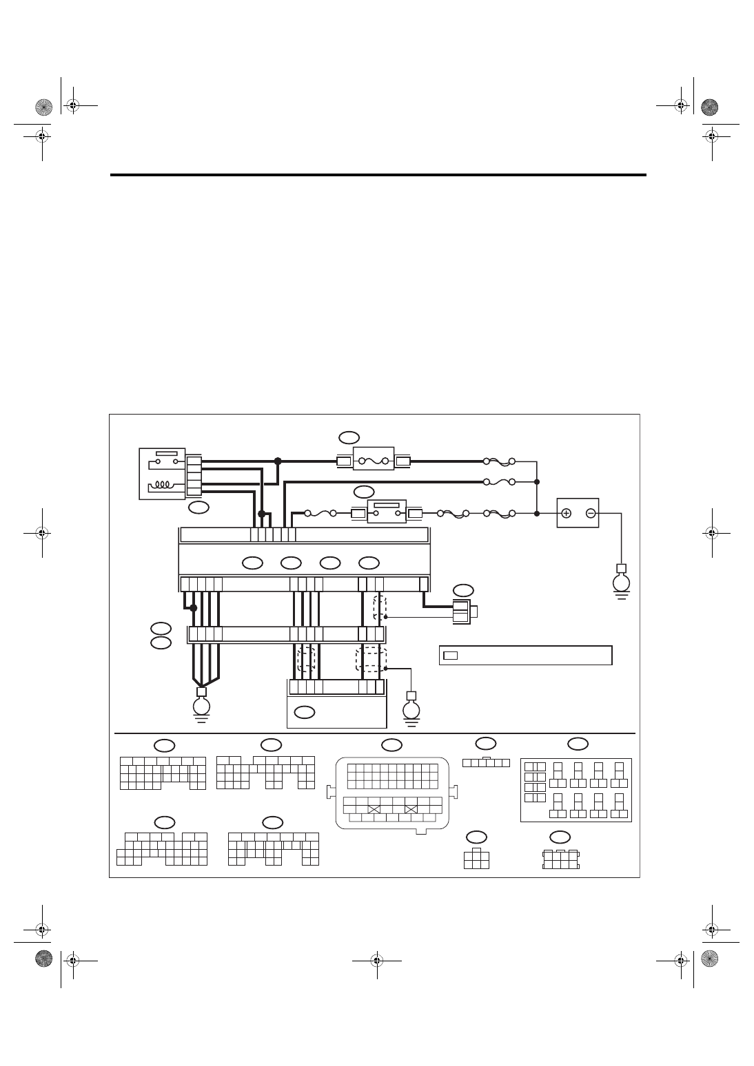
DC:DTC P0606 CONTROL MODULE PROCESSOR
DTC DETECTING CONDITION:
• Immediately at fault recognition
• GENERAL DESCRIPTION <Ref. to GD(H4DOTC)-193, DTC P0606 CONTROL MODULE PROCESSOR,
Diagnostic Trouble Code (DTC) Detecting Criteria.>
TROUBLE SYMPTOM:
• Improper idling
• Poor driving performance
CAUTION:
After servicing or replacing faulty parts, perform Clear Memory Mode <Ref. to EN(H4DOTC)(diag)-63,
OPERATION, Clear Memory Mode.>, and Inspection Mode <Ref. to EN(H4DOTC)(diag)-49, PROCE-
WIRING DIAGRAM:
• Engine electrical system, without SI-DRIVE <Ref. to WI-32, WITHOUT SI-DRIVE, WIRING DIAGRAM,
• Engine electrical system, with SI-DRIVE <Ref. to WI-48, WITH SI-DRIVE, WIRING DIAGRAM, Engine
EN-08738
B135
B:
B134
A:
B137
B136
D:
C:
3
8
39
2
8
6
24
25
*
*
E2
B21
4
6
1
2
3
5
A1
A2
A29
A19
A3
A6
A4
D1
D3
40
34
35
36
A2
8
C4
A1
8
B21
B72
E57
B122
*
B72
C1
D7
B13
C2 C30
24
23
22
21
1
3
15A
B220
B220
B220
3
4
18
19
6
7
4
3
5
2
1
12
11
10
9
8
40
36 39
38
37
34
33
35
32
28 31
30
29
23
22
21
20
26
25
24
27
17
16
15
14
13
2
6
5
4
3
1
32 33
24
15
14
25
31
30
29
35
34
23
22
21
20
19
18
28
27
26
17
16
13
12
11
10
3
9
1
2
8
7
6
5
4
B: B135
A: B134
6
5
4
3
2
1
D: B137
26
25
24
23
22
18
28
27
17
16
15
14
13
31
30
29
21
20
19
12
11
10
4
3
6
5
9
8
7
2
1
C: B136
35
34
33
32
7
26
25
24
23
22
18
28
27
17
16
15
14
13
31
30
29
21
20
19
12
11
10
4
3
6
5
9
8
2
1
B122
8
7
6
5
4
3
2
1
33
32
31
30
29
28
27
26
47
46
45
44
43
42
54
53
52
51
50
49
48
41
40
39
38
37
36
35
34
25
24
23
22
21
20
19
18
17
16
15
14
13
12
11
10
9
8
7
6
5
4
3
2
1
31
30
32
29
34
33
21
20
19
18
17
16
28
27
26
15
14
13
12
11
25
23
22
24
10
3
4
9
1
2
8
7
6
5
E
E
E
SBF-7
SBF-6
ECM
E57
FUSE
(RELAY BLOCK)
IGNITION
SWITCH
BATTERY
MAIN RELAY
No. 13
No. 12
MAIN SBF
: TERMINAL No. OPTIONAL ARRANGEMENT
ELECTRONIC
THROTTLE
CONTROL

EN(H4DOTC)(diag)-294
Diagnostic Procedure with Diagnostic Trouble Code (DTC)
ENGINE (DIAGNOSTICS)
DD:DTC P060A INTERNAL CONTROL MODULE MONITORING PROCESSOR
PERFORMANCE
NOTE:
For the diagnostic procedure, refer to DTC P0606. <Ref. to EN(H4DOTC)(diag)-293, DTC P0606 CONTROL
MODULE PROCESSOR, Diagnostic Procedure with Diagnostic Trouble Code (DTC).>
DE:DTC P060B INTERNAL CONTROL MODULE A/D PROCESSING PERFOR-
MANCE
NOTE:
For the diagnostic procedure, refer to DTC P0606. <Ref. to EN(H4DOTC)(diag)-293, DTC P0606 CONTROL
MODULE PROCESSOR, Diagnostic Procedure with Diagnostic Trouble Code (DTC).>
Step
Check
Yes
No
1
CHECK INPUT VOLTAGE OF ECM.
1) Turn the ignition switch to ON.
2) Measure the voltage between ECM connec-
tor and chassis ground.
Connector & terminal
(B136) No. 1 (+) — Chassis ground (–):
(B137) No. 7 (+) — Chassis ground (–):
Is the voltage 10 — 13 V?
Repair the open or
ground short circuit
of power supply
circuit.
2
CHECK INPUT VOLTAGE OF ECM.
1) Start the engine.
2) Measure the voltage between ECM connec-
tor and chassis ground.
Connector & terminal
(B136) No. 1 (+) — Chassis ground (–):
(B137) No. 7 (+) — Chassis ground (–):
Is the voltage 13 — 15 V?
Repair the open or
ground short circuit
of power supply
circuit.
3
CHECK HARNESS BETWEEN ECM AND
ELECTRONIC THROTTLE CONTROL CON-
NECTOR.
1) Turn the ignition switch to OFF.
2) Disconnect the connectors from ECM and
electronic throttle control.
3) Measure the resistance of harness between
ECM connector and electronic throttle control
connector.
Connector & terminal
(B134) No. 19 — (E57) No. 5:
(B134) No. 29 — (E57) No. 3:
Is the resistance less than 1 Ω? Go to step
Repair the harness
and connector.
NOTE:
In this case, repair
the following item:
• Open circuit in
harness between
ECM
connector
and
electronic
throttle
control
connector
• Poor contact of
coupling connector
4
CHECK ECM GROUND HARNESS.
1) Connect all connectors.
2) Turn the ignition switch to ON.
3) Measure the voltage between ECM connec-
tor and chassis ground.
Connector & terminal
(B134) No. 3 — Chassis ground:
(B134) No. 4 — Chassis ground:
(B134) No. 6 — Chassis ground:
(B137) No. 1 — Chassis ground:
(B137) No. 3 — Chassis ground:
Is the voltage less than 1 V?
Repair the poor
contact of ECM
connector.
Repair the harness
and connector.
NOTE:
In this case, repair
the following item:
• Open circuit in
ground circuit
• Further tighten-
ing of the engine
ground terminal
• Poor contact of
ECM connector
• Poor contact of
coupling connector
EN(H4DOTC)(diag)-295
Diagnostic Procedure with Diagnostic Trouble Code (DTC)
ENGINE (DIAGNOSTICS)
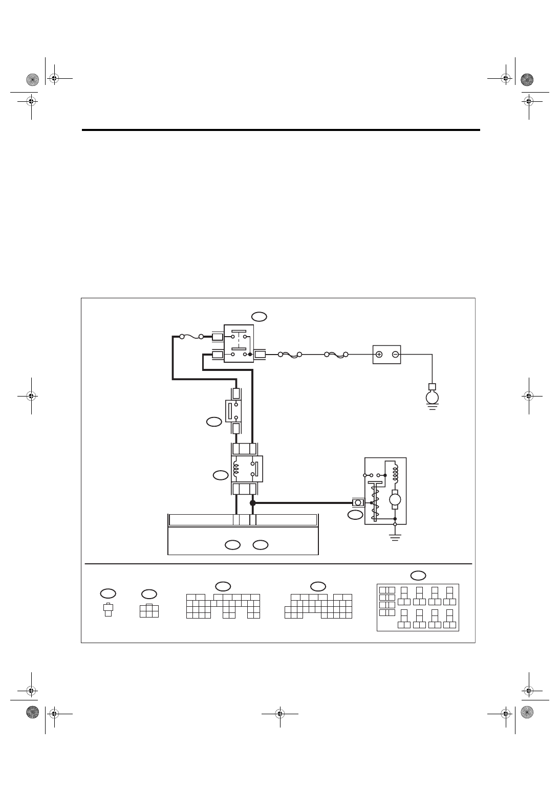
DF:DTC P0616 STARTER RELAY CIRCUIT LOW
DTC DETECTING CONDITION:
• Immediately at fault recognition
• GENERAL DESCRIPTION <Ref. to GD(H4DOTC)-199, DTC P0616 STARTER RELAY CIRCUIT LOW,
Diagnostic Trouble Code (DTC) Detecting Criteria.>
TROUBLE SYMPTOM:
Failure of engine to start
CAUTION:
After servicing or replacing faulty parts, perform Clear Memory Mode <Ref. to EN(H4DOTC)(diag)-63,
OPERATION, Clear Memory Mode.>, and Inspection Mode <Ref. to EN(H4DOTC)(diag)-49, PROCE-
WIRING DIAGRAM:
• Engine electrical system, without SI-DRIVE <Ref. to WI-32, WITHOUT SI-DRIVE, WIRING DIAGRAM,
• Engine electrical system, with SI-DRIVE <Ref. to WI-48, WITH SI-DRIVE, WIRING DIAGRAM, Engine
ECM
13
14
15 16
17
27
24
25
26
20
21
22
23
29
30
31
28
32 35
33
34
37
38
39
36
40
8
9
10
11 12
1
2
5
3
4
7
6
19
18
B225
1
2
B106
B106
1
2
5
6
7
2
1
3
4
29
10 11 12 13 14 15
25
24
16
30
9
8
17 18 19
20
28
21 22 23
32
31
26 27
33
34 35
EN-09249
16
10 11 12 13 14 15
25
24
30
9
8
7
17 18 19 20
28
21 22 23
29
32
31
1
2
3
4
5
6
27
26
33 34 35
B72
1
3
4 5 6
2
6
2
3
B14
B72
C: B136
C: B136
B: B135
B: B135
0
1
2
1
9
1
1
B225
C16
B26
SBF-6
E
M
F/B No. 21
MAIN SBF
BATTERY
IGNITION
SWITCH
STARTER
RELAY
STARTER MOTOR
CLUTCH
START
SWITCH
Нет комментариевНе стесняйтесь поделиться с нами вашим ценным мнением.
Текст