Subaru Impreza 3 / Impreza WRX / Impreza WRX STI. Service manual — part 270
EN(H4DOTC)(diag)-304
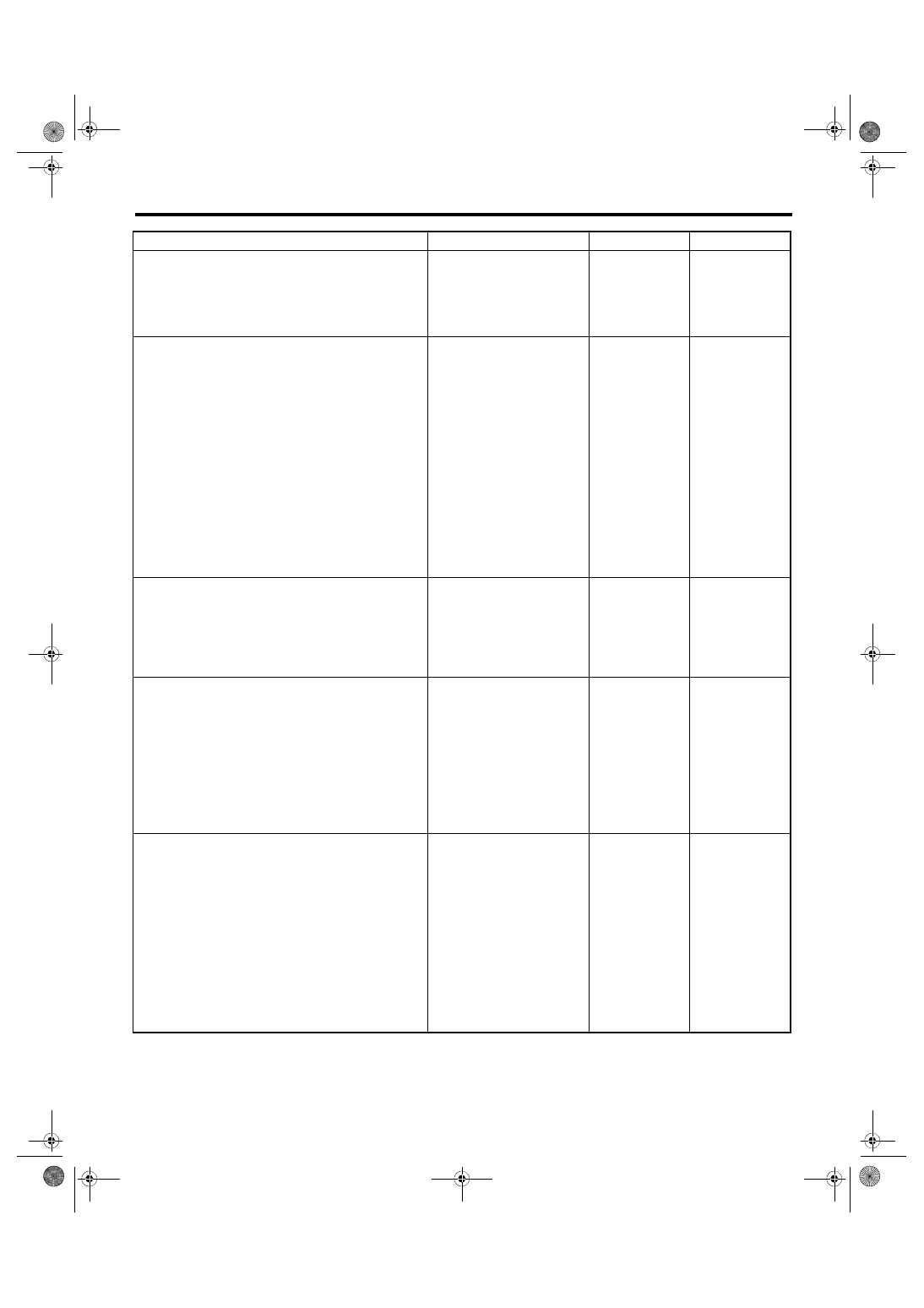
Diagnostic Procedure with Diagnostic Trouble Code (DTC)
ENGINE (DIAGNOSTICS)
Step
Check
Yes
No
1
CHECK OUTPUT SIGNAL OF ECM.
1) Turn the ignition switch to ON.
2) Measure the voltage between ECM connec-
tor and chassis ground.
Connector & terminal
(B135) No. 3 (+) — Chassis ground (–):
Is the voltage 10 V or more?
2
CHECK FOR POOR CONTACT.
Check for poor contact of ECM connector.
Is there poor contact of ECM
connector?
Repair the poor
contact of ECM
connector.
Even if DTC is
detected, the cir-
cuit has returned to
a normal condition
at this time. Repro-
duce the failure,
and then perform
the diagnosis
again.
NOTE:
In this case, tem-
porary open or
short circuit of har-
ness or temporary
poor contact of
connector may be
the cause.
3
CHECK POWER SUPPLY TO PRESSURE
CONTROL SOLENOID VALVE ASSEMBLY.
Measure the voltage between the pressure con-
trol solenoid valve assembly and chassis
ground.
Connector & terminal
(R68) No. 1 (+) — Chassis ground (–):
Is the voltage 10 V or more?
Repair the power
supply circuit.
4
CHECK HARNESS BETWEEN ECM AND
PRESSURE CONTROL SOLENOID VALVE
ASSEMBLY CONNECTOR.
1) Turn the ignition switch to OFF.
2) Disconnect the connectors from the ECM
and pressure control solenoid valve assembly.
3) Measure the resistance between the pres-
sure control solenoid valve assembly connector
and chassis ground.
Connector & terminal
(R68) No. 2 — Chassis ground:
Is the resistance 1 MΩ or
more?
Repair the short
circuit to ground in
harness between
ECM connector
and pressure con-
trol solenoid valve
assembly connec-
tor.
5
CHECK HARNESS BETWEEN ECM AND
PRESSURE CONTROL SOLENOID VALVE
ASSEMBLY CONNECTOR.
Measure the resistance of harness between
ECM connector and pressure control solenoid
valve assembly connector.
Connector & terminal
(B135) No. 3 — (R68) No. 2:
Is the resistance less than 1 Ω? Go to step
Repair the harness
and connector.
NOTE:
In this case, repair
the following item:
• Open circuit in
harness between
ECM
connector
and pressure con-
trol solenoid valve
assembly connec-
tor
• Poor contact of
coupling connector
EN(H4DOTC)(diag)-305
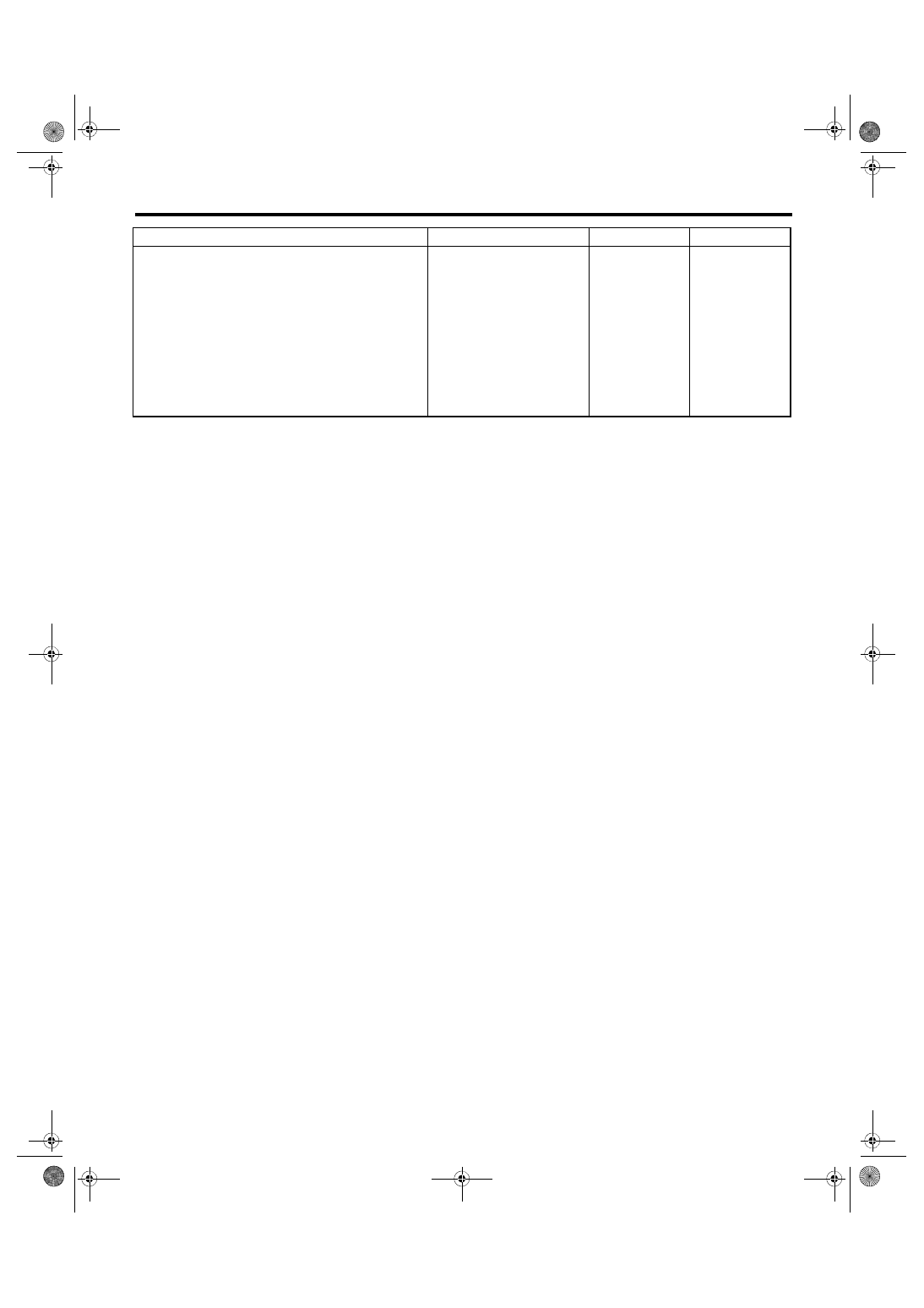
Diagnostic Procedure with Diagnostic Trouble Code (DTC)
ENGINE (DIAGNOSTICS)
6
CHECK PRESSURE CONTROL SOLENOID
VALVE ASSEMBLY.
Measure the resistance between terminals of
pressure control solenoid valve assembly.
Terminals
No. 1 — No. 2:
Is the resistance 10 — 100 Ω? Repair the pres-
sure control sole-
noid valve
assembly connec-
tor for poor con-
tact.
Step
Check
Yes
No
EN(H4DOTC)(diag)-306
Diagnostic Procedure with Diagnostic Trouble Code (DTC)
ENGINE (DIAGNOSTICS)
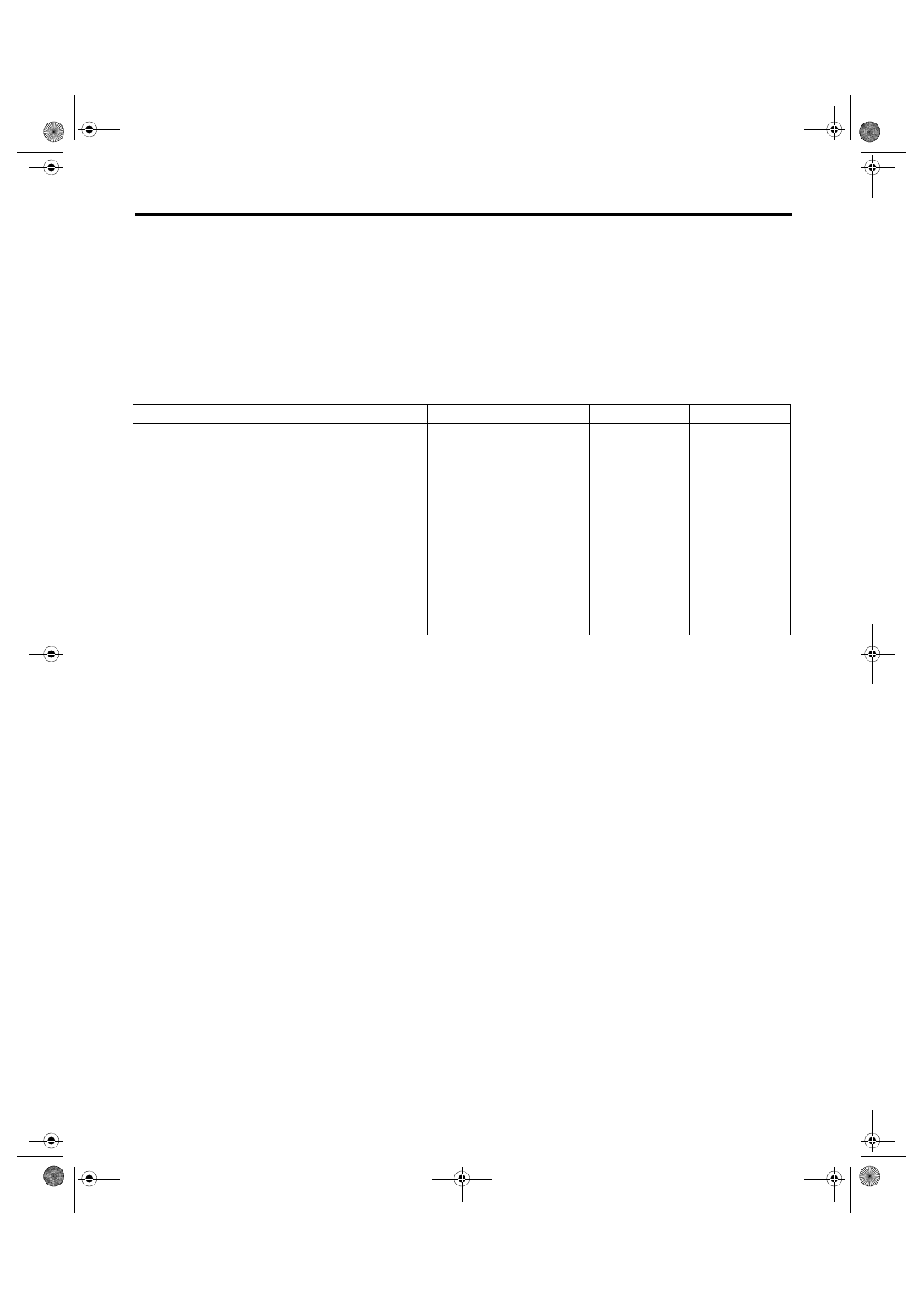
DM:DTC P1410 SECONDARY AIR INJECTION SYSTEM SWITCHING VALVE
STUCK OPEN
DTC DETECTING CONDITION:
• Immediately at fault recognition
• GENERAL DESCRIPTION <Ref. to GD(H4DOTC)-209, DTC P1410 SECONDARY AIR INJECTION SYS-
TEM SWITCHING VALVE STUCK OPEN, Diagnostic Trouble Code (DTC) Detecting Criteria.>
CAUTION:
After servicing or replacing faulty parts, perform Clear Memory Mode <Ref. to EN(H4DOTC)(diag)-63,
OPERATION, Clear Memory Mode.>, and Inspection Mode <Ref. to EN(H4DOTC)(diag)-49, PROCE-
Step
Check
Yes
No
1
CHECK SECONDARY AIR COMBINATION
VALVE.
1) Remove the secondary air combination
valve. <Ref. to EC(STI)-29, Secondary Air
Combination Valve.> <Ref. to EC(w/o STI)-30,
Secondary Air Combination Valve.>
2) Blow in air from the secondary air combina-
tion valve air inlet, and check whether there are
leaks at the pipe connections.
Are there air leaks from the pipe
connections?
EN(H4DOTC)(diag)-307
Diagnostic Procedure with Diagnostic Trouble Code (DTC)
ENGINE (DIAGNOSTICS)
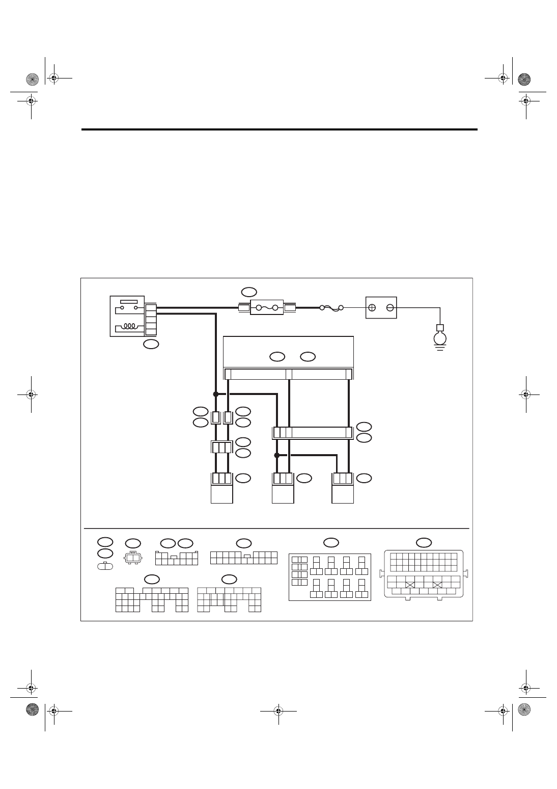
DN:DTC P1420 FUEL TANK PRESSURE CONTROL SOL. VALVE CIRCUIT HIGH
DTC DETECTING CONDITION:
• Detected when 2 consecutive driving cycles with fault occur.
• GENERAL DESCRIPTION <Ref. to GD(H4DOTC)-211, DTC P1420 FUEL TANK PRESSURE CONTROL
SOL. VALVE CIRCUIT HIGH, Diagnostic Trouble Code (DTC) Detecting Criteria.>
CAUTION:
After servicing or replacing faulty parts, perform Clear Memory Mode <Ref. to EN(H4DOTC)(diag)-63,
OPERATION, Clear Memory Mode.>, and Inspection Mode <Ref. to EN(H4DOTC)(diag)-49, PROCE-
WIRING DIAGRAM:
• Engine electrical system, without SI-DRIVE <Ref. to WI-32, WITHOUT SI-DRIVE, WIRING DIAGRAM,
• Engine electrical system, with SI-DRIVE <Ref. to WI-48, WITH SI-DRIVE, WIRING DIAGRAM, Engine
ECM
5
6
7
8
2
1
9
4
3
10
24
22 23
25
11 12 13 14 15
26 27
28
16 17 18 19
20 21
29 30 31
32 33
34 35
B135
B:
5
6
7
8
2
1
9
4
3
10
22 23
11 12 13 14 15
24 25
26
16 17
18 19 20 21
27
28 29
30 31
B137
D:
B21
1 2 3 4 5 6 7 8 9 10 11
12 13 14 15 16 17 18 19 20 21 22
23 24 25 26 27 28 29 30 31 32 33
34 35
42 43
36 37 38 39
48 49 50 51 52 53 54
40 41
44 45
46 47
E52
E4
1 2
B3
D15
D6
E2
B21
44
11
4
8
E4
2
1
E52
2
1
R68
2
1
B135
B:
R57
R15
10
11
R1
B97
R2
B98
7
10
R68
1 2
B220
13
14
15 16
17
27
24
25
26
20
21
22
23
29
30
31
28
32 35
33
34
37
38
39
36
40
8
9
10
11 12
1
2
5
3
4
7
6
19
18
R57
B97
1 2
3 4 5
6 7 8 9 10 11 12
EN-09251
B98
2 3 4 5
6 7 8 9
11 12 13 14
17 18 19 20
1
10
15 16
B220
24
23
22
21
B220
4
3
B137
D:
SBF-7
E
FUSE
(RELAY BLOCK)
MAIN RELAY
BATTERY
PRESSURE CONTROL
SOLENOID VALVE ASSY
PURGE CONTROL
SOLENOID VALVE 2
PURGE CONTROL
SOLENOID VALVE 1
Нет комментариевНе стесняйтесь поделиться с нами вашим ценным мнением.
Текст