Subaru Impreza 3 / Impreza WRX / Impreza WRX STI. Service manual — part 565
BR-45
Brake Hose
BRAKE
C: INSPECTION
Make sure there are no cracks, breakage or dam-
age on hoses. Check the joint for fluid leakage. If
any cracks, breakage, damage or fluid leakage is
found, repair or replace the hose.
BR-46
Brake Pipe
BRAKE
13.Brake Pipe
A: REMOVAL
CAUTION:
• Yellow connectors and harnesses with yel-
low tapes around them are the connectors and
harnesses for the airbag system. Using a tester
above such circuits may cause malfunction of
airbag system. Follow the cautions for the air-
bag system in this case. <Ref. to AB-5, CAU-
• Be careful not to damage the airbag system
wiring harness when servicing the center brake
pipe.
• When removing the brake pipe, do not bend.
NOTE:
The airbag system wiring harness is routed near
the center brake pipe.
B: INSTALLATION
CAUTION:
• Yellow connectors and harnesses with yel-
low tapes around them are the connectors and
harnesses for the airbag system. Using a tester
above such circuits may cause malfunction of
airbag system. Follow the cautions for the air-
bag system in this case. <Ref. to AB-5, CAU-
• Be careful not to damage the airbag system
wiring harness when servicing the center brake
pipe.
• When installing the brake pipe, do not bend.
• After installing the brake pipe and hose, per-
form air bleed.
• After installing the brake hoses, make sure
that they do not contact the tires or suspension
assembly, etc.
NOTE:
The airbag system wiring harness is routed near
the center brake pipe.
Brake pipe tightening torque:
Refer to “COMPONENT” of “General Descrip-
tion”.
Front brake pipes & hoses: <Ref. to BR-9,
FRONT BRAKE PIPES AND HOSES, COM-
Center and rear brake pipes & hoses: <Ref.
to BR-10, CENTER AND REAR BRAKE
PIPES & HOSES, COMPONENT, General
C: INSPECTION
Make sure there are no cracks, breakage or dam-
age on hoses. Check the joint for fluid leakage. If
any cracks, breakage, damage or fluid leakage is
found, repair or replace the pipes.
NOTE:
Use a mirror when inspecting back sides and other
locations which are hard to see.
BR-47
Brake Pedal
BRAKE
14.Brake Pedal
A: REMOVAL
1) Remove the steering column. <Ref. to PS-16,
2) Disconnect the connector from the clutch switch.
3) Disconnect the connector from stop light switch.
4) Remove the stop light switch. <Ref. to BR-49,
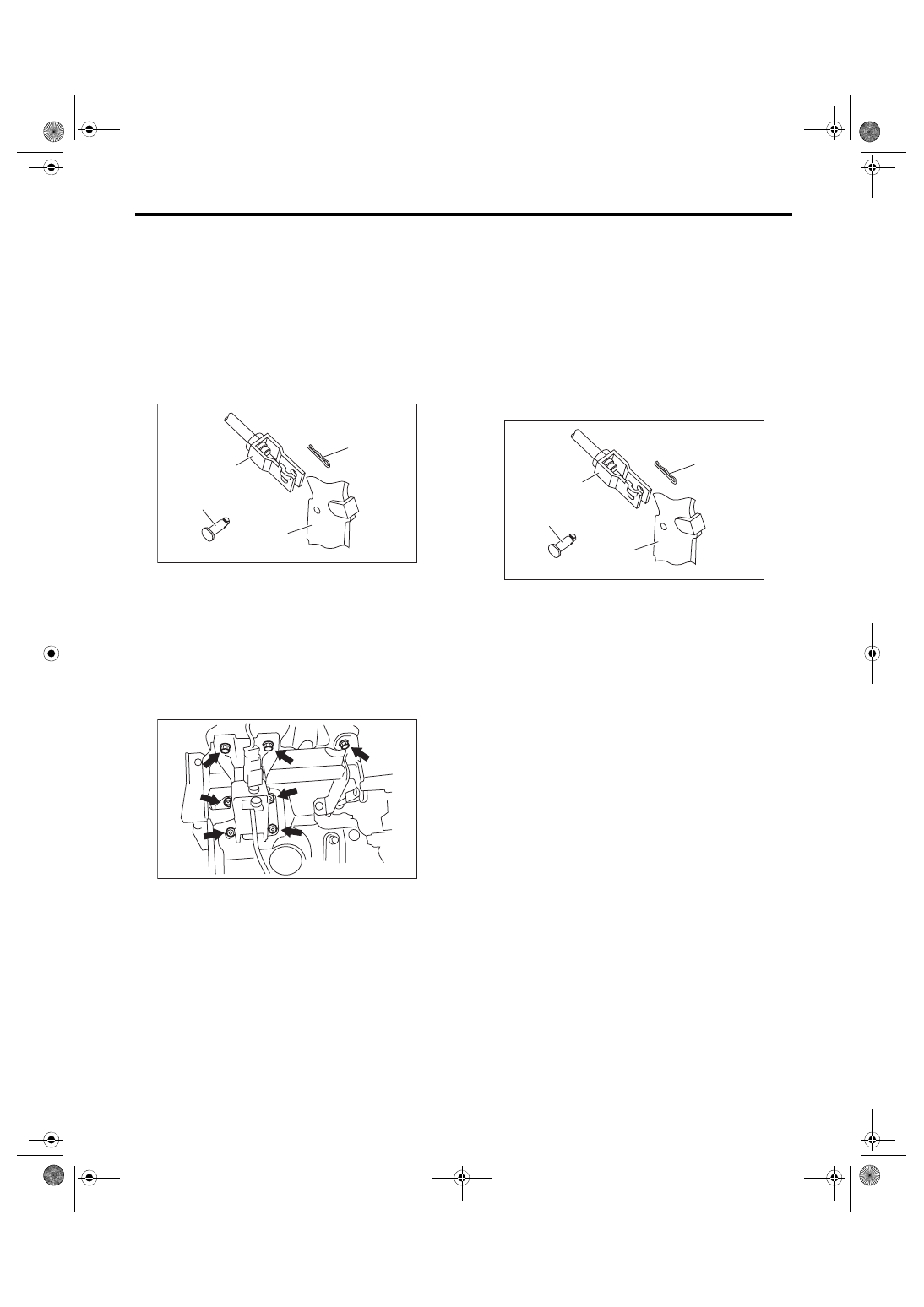
5) Remove the clevis pin which secures the pedal
and operating rod.
6) Remove the nut which secures the clutch master
cylinder.
7) Remove the bolt and nut which secure the brake
pedal bracket.
B: INSTALLATION
1) Install the bolt and nut which secure the brake
pedal bracket.
Tightening torque:
18 N·m (1.84 kgf-m, 13.3 ft-lb)
2) Install clevis pin and snap pin which secure the
operating rod to the brake pedal.
NOTE:
• Replace with a new clevis pin.
• Apply NIGTIGHT LYW No. 2 grease to the clevis
pin.
3) Install the stop light switch. <Ref. to BR-49, IN-
STALLATION, Stop Light Switch.>
4) Check the brake pedal after installation. <Ref. to
BR-48, INSPECTION, Brake Pedal.>
(1) Clevis pin
(2) Snap pin
(3) Operating rod
(4) Brake pedal
(1)
(3)
(4)
(2)
BR-00686
BR-00128
(1) Clevis pin
(2) Snap pin
(3) Operating rod
(4) Brake pedal
(1)
(3)
(4)
(2)
BR-00686
BR-48
Brake Pedal
BRAKE
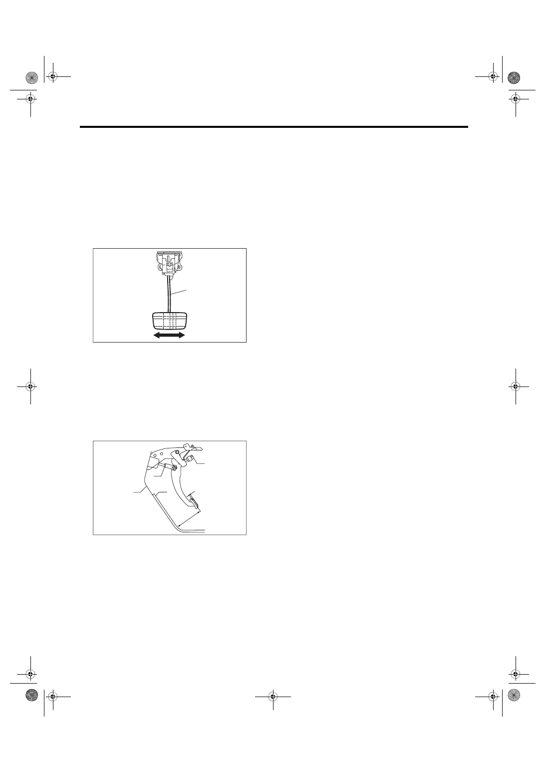
C: INSPECTION
1) Move the brake pedal pads in a horizontal direc-
tion with a force of approx. 10 N (1 kgf, 2 lbf), and
check that the pedal deflection is in the range of
specifications.
CAUTION:
If excessive deflection is noted, replace with a
new bushing.
Deflection of brake pedal:
Limit
5.0 mm (0.197 in) or less
2) Check the position of the pedal pad.
Pedal height L:
150 — 160 mm (5.91 — 6.29 in)
Brake pedal free play A:
0.5 — 2 mm (0.020 — 0.079 in) [When pulling
the brake pedal upward with a force of less
than 10 N (1 kgf, 2 lbf).]
3) Adjust as follows, if the inspection result is not
within the standard value.
(1) Remove the stop light switch. <Ref. to BR-
49, REMOVAL, Stop Light Switch.>
(2) Loosen the lock nut of the brake booster op-
erating rod, and rotate the rod to adjust the ped-
al height L to be within the standard value.
(3) Tighten the lock nut.
Tightening torque:
22 N·m (2.24 kgf-m, 16.2 ft-lb)
(4) Install the stop light switch. <Ref. to BR-49,
INSTALLATION, Stop Light Switch.>
(1) Brake pedal
(1) Stop light switch
(2) Mat
(3) Toe board
(4) Brake booster operating rod
BR-00105
(1)
PM-00452
(1)
(2)
L
A
(3)
(4)
Нет комментариевНе стесняйтесь поделиться с нами вашим ценным мнением.
Текст