Subaru Impreza 3 / Impreza WRX / Impreza WRX STI. Service manual — part 563
BR-37
Brake Booster
BRAKE
1. OPERATION CHECK (WITHOUT GAUG-
ES)
CAUTION:
When checking operation, be sure to apply the
parking brake securely.
• Check without gauges
This method can not determine exactly what part is
defective. But it is possible to identify the outline of
the defect by performing the check according to the
following procedures.
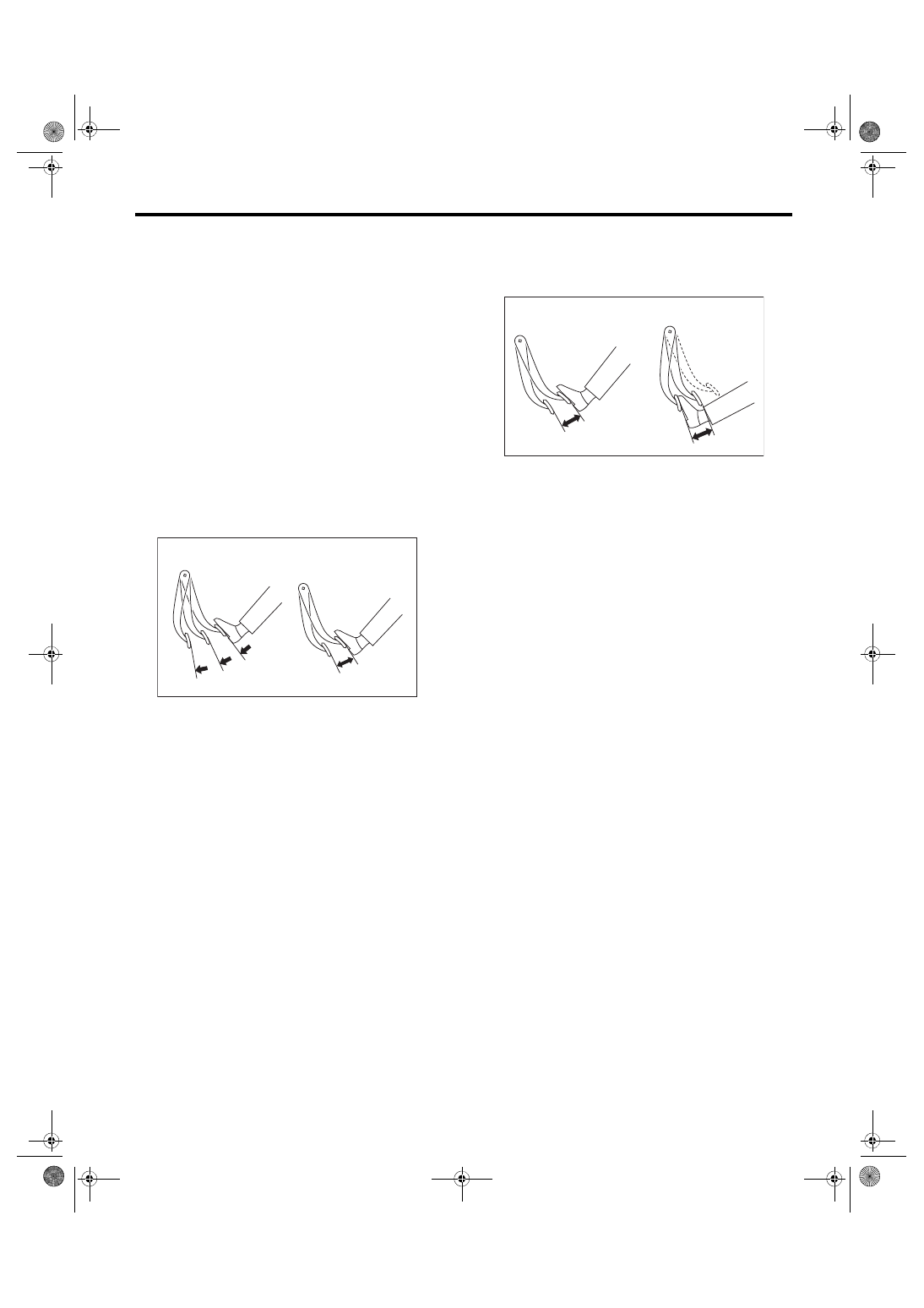
• Air tightness check
Start the engine, and idle it for 1 to 2 minutes, then
turn it OFF. Depress the brake pedal several times
applying the normal pedal force. The pedal stroke
should be the longest at the 1st depression, and it
should become shorter at each successive depres-
sion. If no change occurs in the pedal height when
pressed, the brake booster is faulty.
NOTE:
• In case of defective operation, inspect the condi-
tion of the check valve and vacuum hose as well.
• Replace them if faulty, and perform the test
again.
• If no improvement is observed, check precisely
with gauges.
• Check operation
1) While the engine is OFF, depress the brake ped-
al several times applying the same pedal force, to
check for a change in pedal height.
2) With the brake pedal depressed, start the en-
gine.
3) As the engine starts, the brake pedal should
move slowly toward the floor. If the pedal height
does not change, the brake booster is faulty.
NOTE:
If faulty, check precisely with gauges.
• Loaded air tightness check
Depress the brake pedal while the engine is run-
ning, and turn the engine to OFF while the pedal is
depressed. Keep the pedal depressed for 30 sec-
onds. If the pedal height does not change, the func-
tion of brake booster is normal. If the pedal height
increases, it is faulty.
NOTE:
If faulty, check precisely with gauges.
(1) Normal
(2) Not OK
(3) 1st
(4) 2nd
(5) 3rd
BR-00080
(1)
(3)
(4)
(5)
(2)
(1) When engine is stopped
(2) When engine is started
BR-00081
(1)
(2)
BR-38
Brake Booster
BRAKE
2. OPERATION CHECK (WITH GAUGE)
CAUTION:
When checking operation, be sure to apply the
parking brake securely.
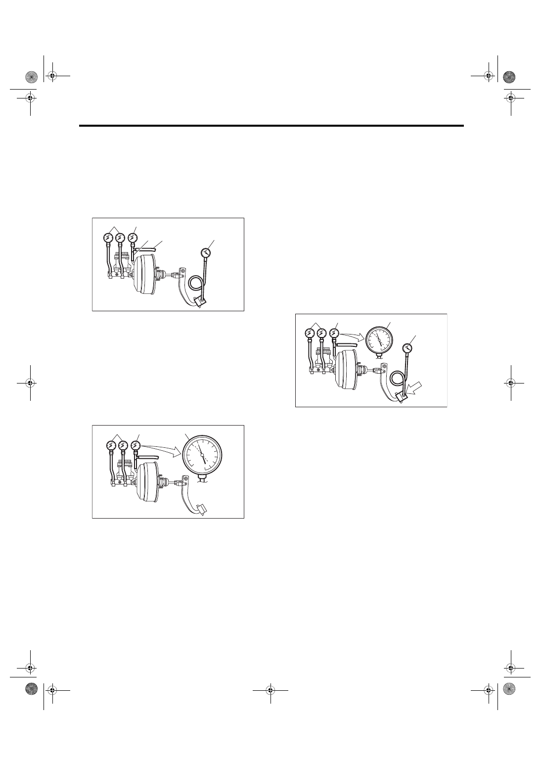
• Check with gauge
Connect the gauge as shown in the figure. After
bleeding air from the pressure gauge, perform each
check.
• Air tightness check
1) Start the engine and keep it running until vacu-
um pressure indicates point A of the vacuum gauge
= 66.7 kPa (500 mmHg, 19.69 inHg). Do not de-
press the brake pedal at this time.
2) Stop the engine and check the gauge. If the vac-
uum pressure drop within 15 seconds after stop-
ping the engine is 3.3 kPa (25 mmHg, 0.98 inHg) or
less, the function of brake booster is normal.
If faulty, the cause may be one of the following.
• Check valve malfunction
• Leak from vacuum hose
• Leak from shell joint section or stud bolt welded
section
• Damaged diaphragm
• Leak from valve body seal and bearing section
• Leak from plate and seal assembly section
• Leak from poppet valve assembly section
• Loaded air tightness check
1) Start the engine and depress the brake pedal
with a pedal force of 196 N (20 kgf, 44 lbf). Keep the
engine running and keep the pedal pressed until a
vacuum of point B = 66.7 kPa (500 mmHg, 19.69
inHg) is indicated on the vacuum gauge.
2) Stop the engine and check the vacuum gauge.
If the vacuum pressure drop within 15 seconds af-
ter stopping the engine is 3.3 kPa (25 mmHg, 0.98
inHg) or less, the function of brake booster is nor-
mal.
If defective, refer to “AIR TIGHTNESS CHECK”.
<Ref. to BR-36, INSPECTION, Brake Booster.>
3) If the brake booster is faulty, replace it with a
new part.
(1) Pressure gauge
(2) Vacuum gauge
(3) Adapter hose
(4) Vacuum hose
(5) Pedal force gauge
(1) Pressure gauge
(2) Vacuum gauge
BR-00082
(1)
(2)
(3) (4)
(5)
BR-00083
(1)
(2)
A
(1) Pressure gauge
(2) Vacuum gauge
(3) Pedal force gauge
(4) Depressed
BR-00084
B
(1)
(2)
(3)
(4)
BR-39
Brake Booster
BRAKE
• Lack of boost action check
Turn the engine OFF, and set the value of the vac-
uum gauge to “0”. Then, check the fluid pressure
when the brake pedal is depressed. The pressure
must be greater than the specification listed.
• Boosting action check
Set the vacuum gauge reading to 66.7 kPa (500
mmHg, 19.69 inHg) with the engine running. Then,
check the fluid pressure when the brake pedal is
depressed. The pressure must be greater than the
specification listed.
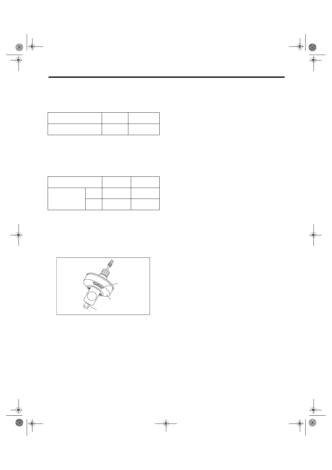
CAUTION:
When replacing the brake booster, adhere the
label to the position shown in the figure. (C0
model)
Label:
C0 model
Part No. 25080GA010
Brake pedal operation force
N (kgf, lbf)
147 (15, 33)
294 (30, 66)
Fluid pressure
kPa (kgf/cm
2
, psi)
545 (6, 79)
1,564 (16, 227)
Brake pedal operation force
N (kgf, lbf)
147 (15, 33)
294 (30, 66)
Fluid pressure
kPa (kgf/cm
2
, psi)
6MT
type
4,984
(51, 723)
10,249
(105, 1,486)
5MT
type
6,003
(61, 871)
11,273
(115, 1,635)
(1) Label
(2) Brake booster
(3) Master cylinder
BR-00484
(1)
(2)
(3)
BR-40
Brake Fluid
BRAKE
10.Brake Fluid
A: INSPECTION
1) Check that the amount of brake fluid is between
the lines of “MIN” and “MAX”. If out of the specified
range, refill or drain the fluid. If the fluid level is
close to “MIN”, check the brake pad for wear and
refill the fluid.
2) Check the fluid for discoloration. If the fluid is ex-
tremely discolored, replace with the new fluid.
B: REPLACEMENT
CAUTION:
• Do not let brake fluid come into contact with
the painted surface of the vehicle body. Wash
away with water immediately and wipe off if it is
spilled by accident.
• Avoid mixing brake fluid of different brands
to prevent fluid performance from degrading.
• Be careful not to allow dirt or dust to enter the
reservoir tank.
NOTE:
• During the operation, keep the reservoir tank
filled with brake fluid to prevent entry of air.
• Operate the brake pedal slowly.
• For convenience and safety, perform the work
with 2 people.
• The required amount of brake fluid is approxi-
mately 500 mL (16.9 US fl oz, 17.6 Imp fl oz) for the
entire brake system.
1) Lift up the vehicle and set rigid racks at the spec-
ified locations, or keep the vehicle lifted.
2) Remove both the front and rear wheels.
3) Drain brake fluid from the reservoir tank.
4) Refill the reservoir tank with recommended
brake fluid.
Recommended brake fluid:
Refer to the “Specifications” in “General De-
scription”. <Ref. to BR-2, SPECIFICATION,
Perform the same procedure as for bleeding the
brake line, until new brake fluid comes out from vi-
Нет комментариевНе стесняйтесь поделиться с нами вашим ценным мнением.
Текст