Subaru Impreza 3 / Impreza WRX / Impreza WRX STI. Service manual — part 455
6MT(diag)-31
Diagnostic Procedure without Diagnostic Trouble Code (DTC)
MANUAL TRANSMISSION AND DIFFERENTIAL (DIAGNOSTICS)
5
CHECK HARNESS BETWEEN BODY INTE-
GRATED UNIT AND PARKING BRAKE
SWITCH.
1) Turn the ignition switch to OFF.
2) Disconnect the connector from body inte-
grated unit.
3) Check for open circuit, short circuit to bat-
tery and short circuit to ground between the
body integrated unit connector and parking
brake switch connector.
Connector & terminal
(B281) No. 15 — (R4) No. 1:
Is the harness normal?
Repair or replace
the harness.
6
CHECK PARKING BRAKE SWITCH.
Measure the resistance between parking brake
switch terminals.
Is the resistance less than 10 Ω
when the parking brake lever is
pulled?
Is the resistance 1 MΩ or more
when the parking brake lever is
lowered?
Replace the body
integrated unit.
Replace the park-
ing brake switch.
7
CHECK DTC.
Check DTC of body integrated unit.
Is the DTC related to CAN dis-
played?
Perform the diag-
nosis according to
DTC.
Check the poor
contact of DCCD
system.
Step
Check
Yes
No
6MT(diag)-32
Diagnostic Procedure without Diagnostic Trouble Code (DTC)
MANUAL TRANSMISSION AND DIFFERENTIAL (DIAGNOSTICS)
C: CHECK DCCD MULTI SELECT SWITCH
DIAGNOSIS:
Input signal of DCCD multi select switch is open or shorted.
TROUBLE SYMPTOM:
• Does not enter the manual mode or auto mode when the mode change switch is pressed.
• Mode does not change in AUTO mode.
• Initial torque can not be changed in manual mode.
NOTE:
Other switch input can not be received if either mode change switch or C.DIFF +/– switch is stuck ON.
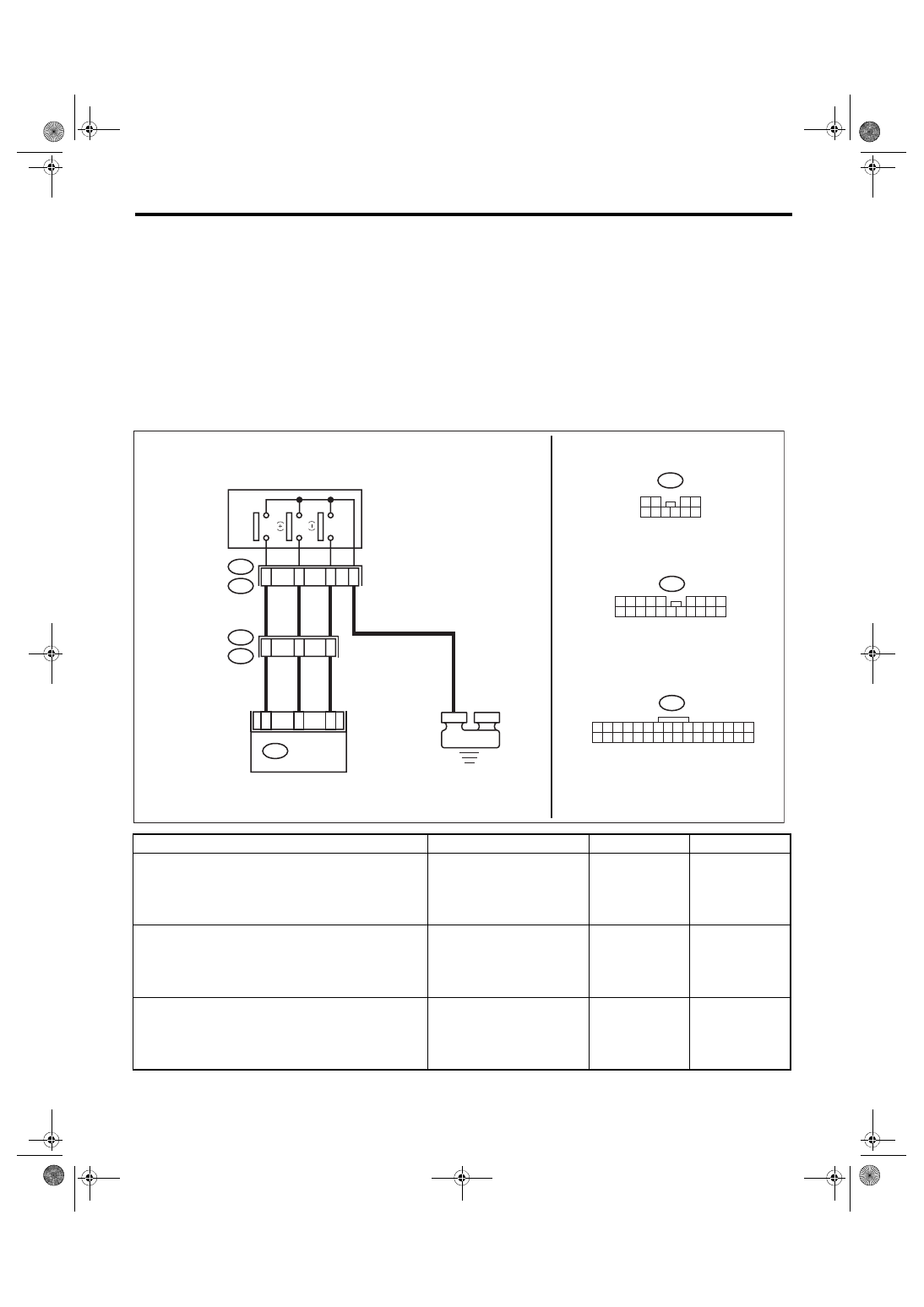
WIRING DIAGRAM:
Step
Check
Yes
No
1
CHECK DCCD CONTROL MODULE.
1) Display the current data «AUTO/MANUAL
Mode Switch» of DCCD control module, using
Subaru Select Monitor.
2) Press the manual mode change switch.
Does the data change from
OFF/ON?
2
CHECK DCCD CONTROL MODULE.
1) Display the current data «Up Switch» of
DCCD control module, using Subaru Select
Monitor.
2) Push the multi select switch toward plus.
Does the data change from
OFF/ON?
3
CHECK DCCD CONTROL MODULE.
1) Display the current data «Down Switch» of
DCCD control module, using Subaru Select
Monitor.
2) Push the multi select switch toward minus.
Does the data change from
OFF/ON?
The switch circuit
is normal.
AD10
32
31
30
29
28
27
26
25
24
23
22
21
20
19
18
17
16
15
14
13
12
11
10
2
10
9
8
7
6
4
3
2
5
1
R33
15
4
1
3
1
9
3
1
B98
R2
R33
4
2
2
6
B380
16
15
10
1
20
9
1
8
1
7
1
4
1
3
1
2
1
1
1
9
6 7 8
5
2 3 4
B98
9
8
7
6
5
4
3
2
1
B380
MT-02941
E
DCCD CM
MULTI SELECT SWITCH (DCCD)
A
UT
O/
MANU
AL
6MT(diag)-33
Diagnostic Procedure without Diagnostic Trouble Code (DTC)
MANUAL TRANSMISSION AND DIFFERENTIAL (DIAGNOSTICS)
4
CHECK MODE CHANGE SWITCH.
1) Disconnect the multi select switch connec-
tor.
2) Press the mode change switch.
3) Using the tester, measure the resistance
between terminals.
Connector & terminal
(AD10) No. 1 — No. 9:
Is the resistance less than 1 Ω? Go to step
5
CHECK MULTI SELECT SWITCH.
1) Push the multi select switch toward plus.
2) Using the tester, measure the resistance
between terminals.
Connector & terminal
(AD10) No. 2 — No. 9:
Is the resistance less than 1 Ω? Go to step
6
CHECK MULTI SELECT SWITCH.
1) Push the multi select switch toward minus.
2) Using the tester, measure the resistance
between terminals.
Connector & terminal
(AD10) No. 3 — No. 9:
Is the resistance less than 1 Ω? Go to step
7
CHECK HARNESS.
Use a tester to measure the resistance between
the multi select switch harness connector and
chassis ground.
Connector & terminal
(R33) No. 9 — Chassis ground:
Is the resistance less than 1 Ω? Go to step
Repair or replace
the ground circuit.
8
CHECK HARNESS.
1) Disconnect the connector from DCCD con-
trol module.
2) Use a tester to measure the resistance
between the DCCD control module and the
multi select switch.
Connector & terminal
(R33) No. 1 — (B380) No. 6:
(R33) No. 2 — (B380) No. 22:
(R33) No. 3 — (B380) No. 4:
Is the resistance less than 1 Ω? Go to step
Repair or replace
the open circuit of
the harness.
9
CHECK HARNESS.
Using the tester, measure the resistance
between terminals.
Connector & terminal
(R33) No. 1 — (R33) No. 2:
(R33) No. 1 — (R33) No. 3:
(R33) No. 3 — (R33) No. 2:
Is the resistance 1 MΩ or
more?
Repair or replace
the short of har-
ness.
10
CHECK HARNESS.
Using the tester, measure the resistance
between terminals.
Connector & terminal
(R33) No. 1 — Chassis ground:
(R33) No. 2 — Chassis ground:
(R33) No. 3 — Chassis ground:
Is the resistance 1 MΩ or
more?
Check the poor
contact.
Repair or replace
the short of har-
ness.
Step
Check
Yes
No
6MT(diag)-34
Diagnostics with Phenomenon
MANUAL TRANSMISSION AND DIFFERENTIAL (DIAGNOSTICS)
15.Diagnostics with Phenomenon
A: INSPECTION
Symptoms
Faulty parts
A tight corner braking symptom occurs.
• VDCCM&H/U
• ABS wheel speed sensor
• Yaw rate & G sensor
• Steering angle sensor
• CAN communication signal
• Center differential
• C.DIFF +/– switch
• Mode change switch
• Tire/Wheel
• DCCD control module
• ECM
• Body integrated unit
An oversteer tendency will become apparent.
• Throttle position sensor
• ECM
• C.DIFF +/– switch
• Mode change switch
• Tire/Wheel
• DCCD control module
• Center differential
• DCCD relay
• Rear differential oil temperature switch
• Neutral position switch
• Steering angle sensor
• VDCCM&H/U
• CAN communication signal
• Body integrated unit
• Yaw rate & G sensor
A tendency to understeer occurs during high speed cornering.
• VDCCM&H/U
• ABS wheel speed sensor
• CAN communication signal
• Throttle position sensor
• Yaw rate & G sensor
• Center differential
• ECM
• Engine speed signal
• Neutral position switch
• Steering angle sensor
• Body integrated unit
Torque characteristics of the center differential do not change.
• C.DIFF +/– switch
• DCCD relay
• Center differential
• DCCD control module
DCCD indicator does not operate. (is not displayed)
• Combination meter
• DCCD control module
DCCD indicator does not operate even when the C.DIFF +/–
switch is operated. (Displayed but does not change. or, the dis-
play blinks.)
• C.DIFF +/– switch
• Combination meter
• DCCD control module
DCCD AUTO mode does not operate even when the C.DIFF +/–
switch is operated. (Displayed but does not change.)
• Mode change switch
• Combination meter
• DCCD control module
• Body integrated unit
• CAN communication signal
Нет комментариевНе стесняйтесь поделиться с нами вашим ценным мнением.
Текст