Subaru Impreza 3 / Impreza WRX / Impreza WRX STI. Service manual — part 453
6MT(diag)-23
Diagnostic Procedure with Diagnostic Trouble Code (DTC)
MANUAL TRANSMISSION AND DIFFERENTIAL (DIAGNOSTICS)
D: DTC P1769 YAW RATE & LATERAL G SENSOR MALFUNCTION
DIAGNOSIS:
Malfunction information transmitted from the yaw rate & G sensor
TROUBLE SYMPTOM:
A tendency to understeer occurs during high speed cornering.
Step
Check
Yes
No
1
CHECK DTC.
Does the DTC related to G sen-
sor or yaw rate sensor appear
in the VDC diagnostics test
mode?
Perform the diag-
nosis according to
DTC.
2
CHECK IGNITION POWER SUPPLY CIRCUIT
OF DCCD CONTROL MODULE.
1) Connect the Subaru Select Monitor to the
vehicle.
2) Turn the ignition switch to ON.
3) Read the data of «Battery voltage» using
Subaru Select Monitor.
Is the voltage 11 V or more?
Repair the open
circuit of harness
between fuse (F/B
No. 12) and DCCD
control module, or
between fuse (F/B
No. 12) and bat-
tery.
3
CHECK DTC.
Is DTC P1720 displayed?
Perform the diag-
nosis according to
DTC.
4
CHECK DCCD CONTROL MODULE.
1) Drive the vehicle on a flat road.
2) Stop the vehicle with the front wheels in a
straight forward direction.
3) Read the data of «Yaw Rate» and «Lateral
G» using the Subaru Select Monitor.
Does the yaw rate and lateral G
value change according to the
vehicle behavior? When the
vehicle stops, is the yaw rate
value within –4 — 4 deg/s, and
also is the lateral G value within
–1.5 — 1.5 m/s
2
?
5
CHECK DTC.
1) Clear the memory.
2) Start the engine.
3) Read the DTC.
Is DTC P1769 displayed?
Replace the yaw
rate & G sensor.
6
CHECK OTHER DTC.
Is a DTC other than DTC P1769
displayed?
Perform the diag-
nosis according to
DTC.
Yaw rate & G sen-
sors are currently
normal.
6MT(diag)-24
Diagnostic Procedure with Diagnostic Trouble Code (DTC)
MANUAL TRANSMISSION AND DIFFERENTIAL (DIAGNOSTICS)
E: DTC P1875 CIRCUIT OF CENTER DIFF
DIAGNOSIS:
Center differential output signal circuit is open or shorted.
TROUBLE SYMPTOM:
• Center differential does not operate.
• The lock ratio of the center differential does not change, or malfunction occurs.
• A tight corner braking symptom occurs.
• An oversteer tendency will become apparent.
• A tendency to understeer occurs during high speed cornering.
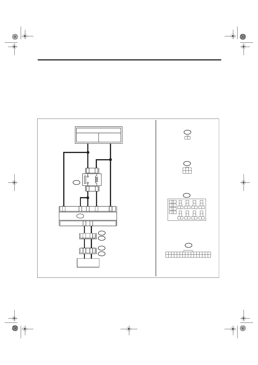
WIRING DIAGRAM:
32
31
30
29
28
27
26
25
24
23
22
21
20
19
18
17
16
15
14
13
12
11
10
2
1
T16
2
6
4 5
3
1
B128
18
19
6
7
4
3
5
2
1
12
1
1
10
9
8
40
36 39
38
37
34
33
35
32
28 31
30
29
23
22
21
20
26
25
24
27
17
16
5
1
14
13
B220
12
11
7
2
1
6
2
5
2
7
2
8
2
B220
T17
T16
T9
1
4
32
15
14
13
9
8
7
6
5
4
3
2
1
B380
B128
B380
MT-02345
CENTER
DIFFERENTIAL
TO POWER SUPPLY CIRCUIT
DCCD RELAY
MB-26
M/B FUSE NO. 12
(B)
FB-38
F/B FUSE NO. 12
(IG)
DCCD CM
6MT(diag)-25
Diagnostic Procedure with Diagnostic Trouble Code (DTC)
MANUAL TRANSMISSION AND DIFFERENTIAL (DIAGNOSTICS)
Step
Check
Yes
No
1
CHECK HARNESS BETWEEN DCCD CON-
TROL MODULE AND TRANSMISSION HAR-
NESS.
1) Turn the ignition switch to OFF.
2) Disconnect the DCCD control module har-
ness connector.
3) Disconnect the transmission harness con-
nector and the bulk harness connector.
4) Measure resistance of the harness between
DCCD control module harness connector and
the transmission harness connector.
Connector & terminal
(B380) No. 15 — (B128) No. 1:
(B380) No. 32 — (B128) No. 4:
Is the resistance less than 1 Ω? Go to step
Repair the bulk
harness open cir-
cuit between
DCCD control
module and trans-
mission harness.
2
CHECK HARNESS BETWEEN DCCD CON-
TROL MODULE AND TRANSMISSION HAR-
NESS.
Measure the resistance between DCCD control
module harness connector and chassis ground.
Connector & terminal
(B380) No. 15 — Chassis ground:
(B380) No. 32 — Chassis ground:
Is the resistance 1 MΩ or
more?
Repair the bulk
harness short cir-
cuit between
DCCD control
module and trans-
mission harness.
3
CHECK CENTER DIFFERENTIAL.
Measure the resistance between transmission
harness connector terminals.
Connector & terminal
(T9) No. 1 — No. 4:
Is the resistance 1.2 — 2.5 Ω? Go to step
Replace the center
differential.
4
CHECK OUTPUT SIGNAL OF DCCD CON-
TROL MODULE.
1) Connect all harness connectors.
2) Turn the ignition switch to ON.
3) Release the parking brake.
4) Press the mode change switch to enter the
manual mode.
5) Press the C.DIFF +/– switch to enter the
lock position.
6) Measure the voltage between DCCD con-
trol module harness connectors.
Connector & terminal
(B380) No. 15 (+) — No. 32 (–):
Is the voltage 5.5 — 8.0 V?
5
CHECK OUTPUT SIGNAL OF DCCD CON-
TROL MODULE.
1) Move the C.DIFF +/– switch from the differ-
ential lock position to the differential free posi-
tion.
2) Read the voltage between DCCD control
module harness connectors.
Connector & terminal
(B380) No. 15 (+) — No. 32 (–):
Does the voltage drop in stages
according to the DCCD manual
mode display?
Circuit is currently
operating properly.
6MT(diag)-26
Diagnostic Procedure with Diagnostic Trouble Code (DTC)
MANUAL TRANSMISSION AND DIFFERENTIAL (DIAGNOSTICS)
6
CHECK FUSE (M/B NO. 12).
1) Turn the ignition switch to OFF.
2) Remove the fuse (M/B No. 12).
Is the fuse (M/B No. 12) blown
out?
Replace the fuse
(M/B No. 12). If the
new fuse (M/B No.
12) has blown out
easily, check for
the short circuit to
chassis ground of
harness between
fuse (M/B No. 12)
and DCCD control
module, or
between fuse (M/B
No. 12) and relay.
7
CHECK POWER SUPPLY CIRCUIT OF DCCD
RELAY.
1) Install the fuse.
2) Turn the ignition switch to OFF.
3) Disconnect the DCCD relay harness con-
nector.
4) Measure the voltage between DCCD relay
harness connector and chassis ground.
Connector & terminal
(B220) No. 25 (+) — Chassis ground (–):
Is the voltage 10 V or more?
Repair the open or
short circuit
between fuse (M/B
No. 12), DCCD
relay, and battery.
8
CHECK IGNITION POWER SUPPLY CIRCUIT
OF DCCD RELAY.
1) Turn the ignition switch to ON.
2) Measure the voltage between DCCD relay
and chassis ground.
Connector & terminal
(B220) No. 27 (+) — Chassis ground (–):
Is the voltage 10 V or more?
Repair the open
circuit between
fuse (F/B No. 12),
DCCD relay, and
battery.
9
CHECK HARNESS BETWEEN DCCD CON-
TROL MODULE AND DCCD RELAY.
1) Turn the ignition switch to OFF.
2) Disconnect the connector from DCCD con-
trol module.
3) Measure resistance of the harness between
DCCD control module connector and DCCD
relay connector.
Connector & terminal
(B380) No. 7 — (B220) No. 28:
(B380) No. 13 — (B220) No. 26:
(B380) No. 14 — (B220) No. 26:
Is the resistance less than 1 Ω? Go to step
Repair the open
circuit of harness
between DCCD
control module
connector and
DCCD relay con-
nector.
10
CHECK HARNESS BETWEEN DCCD CON-
TROL MODULE AND DCCD RELAY.
Measure the resistance of harness between
DCCD control module connector and chassis
ground.
Connector & terminal
(B380) No. 7 — Chassis ground:
(B380) No. 13 — Chassis ground:
(B380) No. 14 — Chassis ground:
Is the resistance 1 MΩ or
more?
Repair the short
circuit of harness
between DCCD
control module
connector and
DCCD relay con-
nector.
11
CHECK DCCD RELAY.
Measure the resistance between DCCD relay
terminals.
Connector & terminal
(B220) No. 25 — No. 26:
Is the resistance 1 MΩ or
more?
Replace the DCCD
relay.
Step
Check
Yes
No
Нет комментариевНе стесняйтесь поделиться с нами вашим ценным мнением.
Текст