Subaru Impreza 3 / Impreza WRX / Impreza WRX STI. Service manual — part 454
6MT(diag)-27
Diagnostic Procedure with Diagnostic Trouble Code (DTC)
MANUAL TRANSMISSION AND DIFFERENTIAL (DIAGNOSTICS)
12
CHECK DCCD RELAY.
Connect the battery positive lead to terminal
No. 27 and the negative lead to terminal No. 28,
then measure the resistance between DCCD
relay terminals.
Connector & terminal
(B220) No. 25 — No. 26:
Is the resistance less than 1 Ω? Go to step
Replace the DCCD
relay.
13
CHECK DCCD CONTROL MODULE RELAY
DRIVE CIRCUIT.
1) Connect all connectors.
2) Turn the ignition switch to ON.
3) Measure the voltage between DCCD con-
trol module and chassis ground.
Connector & terminal
(B380) No. 7 (+) — Chassis ground (–):
Is the voltage less than 1 V?
14
CHECK IGNITION POWER SUPPLY CIRCUIT
OF DCCD CONTROL MODULE.
Measure the voltage between DCCD control
module and chassis ground.
Connector & terminal
(B380) No. 13 (+) — Chassis ground (–):
(B380) No. 14 (+) — Chassis ground (–):
Is the voltage 8 V or more?
15
CHECK CENTER DIFFERENTIAL.
1) Turn the ignition switch to OFF.
2) Connect the Subaru Select Monitor to data
link connector.
3) Turn the ignition switch to ON.
4) Run the Subaru Select Monitor.
5) Press the mode change switch to enter the
manual mode.
6) Release the parking brake.
7) Press the C.DIFF +/– switch to enter the
lock position.
8) Read the data of «C-Diff. Indicate Current»
and «C-Diff. Real Current» using Subaru Select
Monitor.
Are «C-Diff. Indicate Current»
and «C-Diff. Real Current» both
approximately 3.6 — 4.0 A?
16
CHECK CENTER DIFFERENTIAL.
1) Using Subaru Select Monitor, operate the
C.DIFF +/– switch so that «C-Diff. Indicate Cur-
rent» becomes 1.6A.
2) Read the data of «C-Diff. Real Current»
using Subaru Select Monitor.
Is «C-Diff. Real Current» about
the same as «C-Diff. Indicate
Current»?
17
CHECK POOR CONTACT OF HARNESS
CONNECTORS.
Is there poor contact of the har-
ness connector?
Repair the poor
contact.
18
Is P1875 displayed?
Check the poor
contact.
19
CHECK DTC.
Are DTCs other than P1875
displayed?
Perform the diag-
nosis according to
DTC.
The center differ-
ential circuit is cur-
rently operating
properly.
Step
Check
Yes
No
6MT(diag)-28
Diagnostic Procedure without Diagnostic Trouble Code (DTC)
MANUAL TRANSMISSION AND DIFFERENTIAL (DIAGNOSTICS)
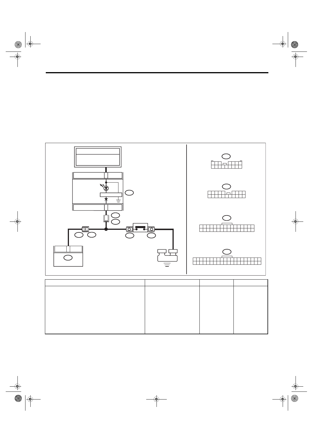
14.Diagnostic Procedure without Diagnostic Trouble Code (DTC)
A: CHECK REAR DIFFERENTIAL OIL TEMPERATURE SWITCH
DIAGNOSIS:
Input signal circuit of rear differential oil temperature switch is open or shorted.
TROUBLE SYMPTOM:
• Center differential remains free
• An oversteer tendency will become apparent.
• Rear differential oil temperature warning light illuminates.
WIRING DIAGRAM:
Step
Check
Yes
No
1
CHECK REAR DIFFERENTIAL OIL TEMPER-
ATURE SWITCH WARNING LIGHT CIRCUIT.
1) Turn the ignition switch to OFF.
2) Disconnect the DCCD control module har-
ness connector.
3) Turn the ignition switch to ON.
4) Measure the voltage of the rear differential
oil temperature switch.
Connector & terminal
(B380) No. 5 (+) — Chassis ground (–):
Is the voltage less than 0.4 V? Go to step
17 18 19 20 21 22 23 24 25 26 27 28 29 30 31 32
16
15
14
13
12
11
10
40
2
5
B380
8
i10
16
15
10
1
20
9
1
8
1
7
1
4
1
3
1
2
1
1
1
9
6 7 8
5
2 3 4
B92
i102
40
39
8
3
7
3
6
3
5
3
34
3
3
2
3
1
3
0
3
9
2
8
2
7
2
6
2
5
2
4
2
3
2
2
2
1
2
20
9
1
8
1
7
1
6
1
5
1
4
1
3
1
2
1
1
1
0
1
9
1 2 3 4 5 6 7 8
i10
16
15
14
13
12
11
10
9
8
7
6
5
4
3
2
1
9
8
7
6
5
4
3
2
1
B380
R5
B92
R159
R148
i102
R167
MT-02318
E
FB-36
F/B FUSE NO. 5
(IG)
REAR DIFFERENTIAL
OIL TEMPERATURE SWITCH
COMBINATION
METER
TO POWER SUPPLY CIRCUIT
REVERSE CIRCUIT
REAR
DIFFERENTIAL
OIL TEMPERATURE
WARNING LIGHT
DCCD CM
6MT(diag)-29
Diagnostic Procedure without Diagnostic Trouble Code (DTC)
MANUAL TRANSMISSION AND DIFFERENTIAL (DIAGNOSTICS)
2
CHECK HARNESS BETWEEN DCCD CON-
TROL MODULE AND COMBINATION
METER.
1) Turn the ignition switch to OFF.
2) Disconnect the harness connector from the
combination meter.
3) Disconnect the connector from the rear dif-
ferential oil temperature switch.
4) Measure the resistance between combina-
tion meter and DCCD control module harness
connectors.
Connector & terminal
(B380) No. 5 — (i10) No. 40:
Is the resistance less than 1 Ω? Go to step
Repair the open
circuit between
DCCD control
module and the
combination meter.
3
CHECK HARNESS BETWEEN DCCD CON-
TROL MODULE AND REAR DIFFERENTIAL
OIL TEMPERATURE SWITCH.
Measure the resistance between DCCD control
module harness connector and rear differential
oil temperature switch harness connector.
Connector & terminal
(B380) No. 5 — (R148) No. 1:
Is the resistance less than 1 Ω? Go to step
Repair the open
circuit between
DCCD control
module and rear
differential oil tem-
perature switch.
4
CHECK REAR DIFFERENTIAL OIL TEMPER-
ATURE SWITCH GROUND CIRCUIT.
1) Disconnect the harness connector from the
bracket ground of the rear differential.
2) Measure the resistance between the rear
differential oil temperature switch ground har-
ness connector and chassis ground.
Connector & terminal
(R159) No. 1 — Chassis ground:
Is the resistance 1 MΩ or
more?
Repair the open
circuit of the rear
differential oil tem-
perature switch
ground circuit, and
contact failure of
the harness con-
nector.
5
CHECK REAR DIFFERENTIAL OIL TEMPER-
ATURE SWITCH.
Measure the resistance between the rear differ-
ential oil temperature switch and the rear differ-
ential oil temperature switch body.
Connector & terminal
(R148) No. 1 — Rear differential oil tem-
perature switch body:
Is the resistance less than 1 Ω? Go to step
Replace the rear
differential oil tem-
perature switch.
6
CHECK REAR DIFFERENTIAL OIL TEMPER-
ATURE WARNING LIGHT.
1) Turn the ignition switch to ON.
2) Short the chassis ground and the combina-
tion meter harness connector.
Connector & terminal
(i10) No. 40 (+) — Chassis ground (–):
Does the rear differential oil
temperature light turn OFF?
Check the poor
contact.
Check the combi-
nation meter.
Step
Check
Yes
No
6MT(diag)-30
Diagnostic Procedure without Diagnostic Trouble Code (DTC)
MANUAL TRANSMISSION AND DIFFERENTIAL (DIAGNOSTICS)
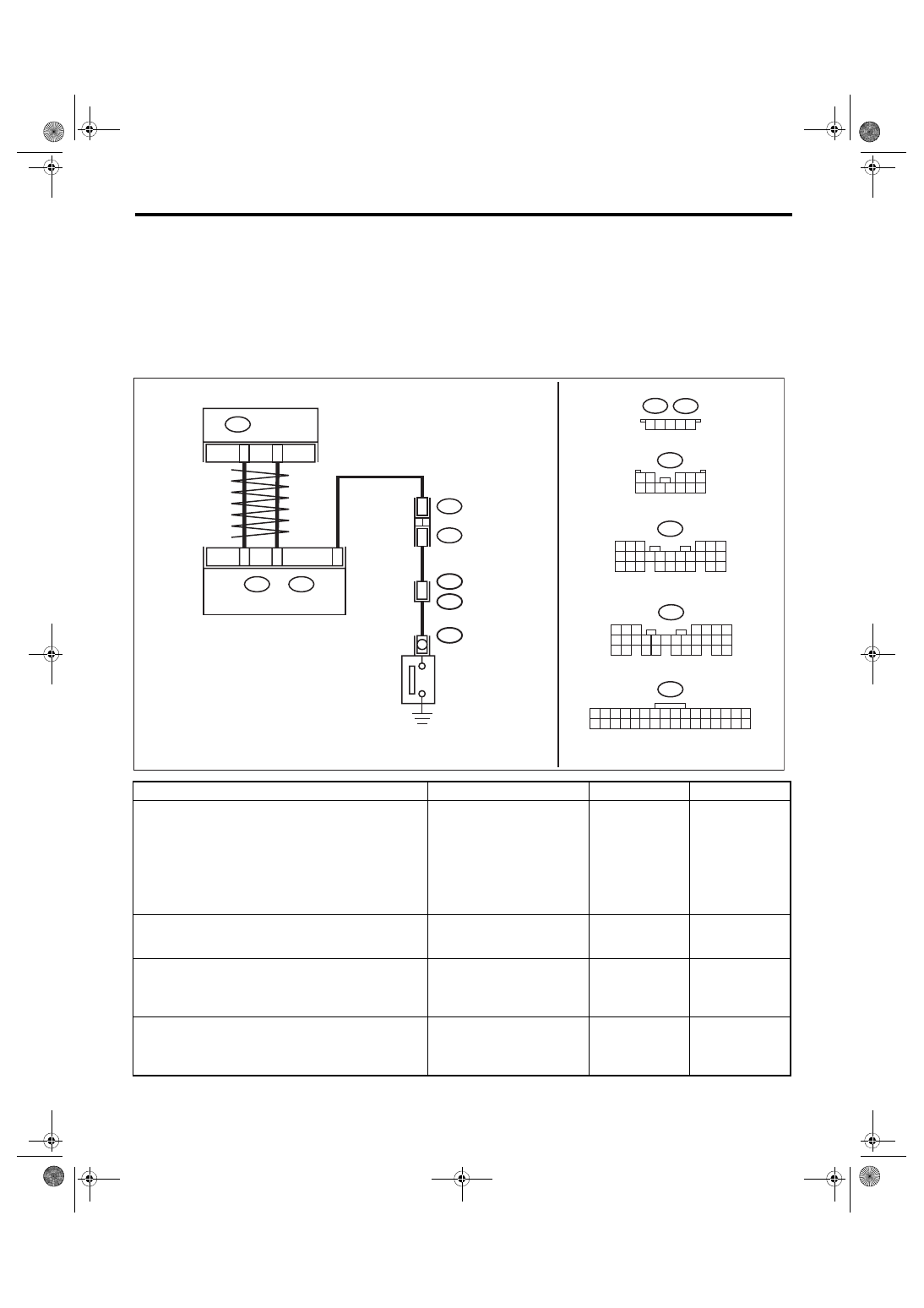
B: CHECK PARKING BRAKE SWITCH
DIAGNOSIS:
Input signal circuit of parking brake switch is open or shorted.
TROUBLE SYMPTOM:
• It does not show a differential free tendency even when the parking brake switch is applied.
• Remains differential free even when the parking brake switch is released.
WIRING DIAGRAM:
Step
Check
Yes
No
1
CHECK IGNITION CIRCUIT OF DCCD CON-
TROL MODULE.
1) Connect the Subaru Select Monitor to the
vehicle.
2) Turn the ignition switch to ON.
3) Read the data of «Battery voltage» using
Subaru Select Monitor.
Is the voltage 11 V or more?
Repair the open
circuit of harness
between fuse (F/B
No. 12) and DCCD
control module, or
between fuse (F/B
No. 12) and bat-
tery.
2
CHECK DTC.
Is DTC P1720 displayed?
Perform the diag-
nosis according to
DTC.
3
CHECK DCCD CONTROL MODULE.
1) Operate the parking brake lever.
2) Read the data of «Parking Position Switch»
using Subaru Select Monitor.
Is the ON/OFF normally
detected?
The parking brake
switch circuit is
currently operating
properly.
4
CHECK BODY INTEGRATED UNIT.
1) Operate the parking brake lever.
2) Read the data of «Parking Position Switch»
using Subaru Select Monitor.
Is the ON/OFF normally
detected?
3
3
1 2 3 4 5
B437
B438
B438
B437
B99
1 2
3 4 5
6 7 8 9 10 11 12
B380
2
1
3 4
6
5
7 8 9 10 11 12 13 14 15 16
17 18 19 20 21 22 23 24 25 26 27 28 29 30 31 32
B280
B:
6
4 5
3
1 2
9
7 8
7
1
6
1
5
1
4
1
3
1
2
1
1
1
0
1
0
2
9
1
8
1
4
2
3
2
2
2
1
2
6
2
5
2
5
R3
B99
R4
C15
B281
C:
7
5 6
8
2
1
9
4
3
10
24 25
3
2
2
2
11 12 13 14 15
28
7
2
6
2
16 17 18 19
21
0
2
C: B281
B: B280
1
8
B3
B9
2
B380
MT-02931
DCCD CM
BODY INTEGRATED UNIT
PARKING BRAKE
SWITCH
Нет комментариевНе стесняйтесь поделиться с нами вашим ценным мнением.
Текст