Subaru Impreza 3 / Impreza WRX / Impreza WRX STI. Service manual — part 703
IDI-3
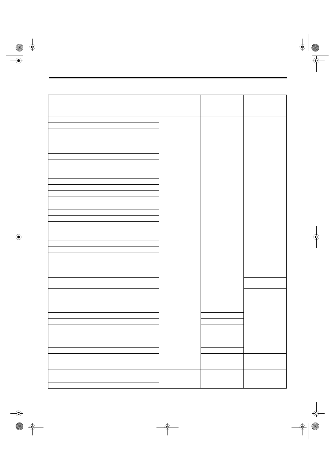
General Description
INSTRUMENTATION/DRIVER INFO
STI model
• Combination meter
Meter, display
Operation method,
display method
Drive control
When checking the
indicator needle
operation/needle
reading operation
Speedometer
Stepping motor type
Combination meter
Light ON
Tachometer
Engine coolant temperature gauge
Fuel gauge
ABS warning light
LED
Combination meter
On/Off
Seat belt warning light
Door open warning light
Tire pressure warning light
Hill start assist warning light
HI-beam indicator light
[I] Indicator light
[S] Indicator light
[S#] Indicator light
AUTO [–] indicator light
AUTO [+] indicator light
AUTO indicator light
REV indicator light
Shift-up indicator light
Cruise indicator light
Cruise set indicator light
Front fog light indicator light
Light illumination indicator light
Oil pressure warning light
Meter illumination back light
Light ON
LCD back light
VDC warning light/VDC indicator light (yellow)
On (yellow)/Off
VDC OFF (yellow)/VDC traction mode indicator light
(green)
Off/On (green)
Fuel level warning light
On/Off (Turns on
near E)
Malfunction indicator light
ECM
Turns on or off
according to module
control
Oil pressure warning light
Oil pressure switch
Airbag warning light
Airbag CM
Charge warning light
Generator
Rear differential oil temperature warning light
Rear differential oil
temperature switch
Turn signal indicator light
Turn signal and haz-
ard unit
Security/immobilizer indicator light
Body integrated unit
Brake fluid/parking brake warning light
Combination meter/
brake fluid level
switch
On/Turns on or off
according to module
control
Odo/Trip indicator
LCD
Combination meter
—
DCCD torque indicator
REV indicator
IDI-4
General Description
INSTRUMENTATION/DRIVER INFO
• Clock
B: CAUTION
• Before disassembling or reassembling parts, always disconnect the battery ground cable from battery.
When replacing the audio, control module and other parts provided with memory functions, record the mem-
ory contents before disconnecting the battery ground cable. Otherwise, the memory is cleared.
• Reassemble the parts in the reverse order of disassembly procedure unless otherwise indicated.
• Use gloves to avoid damage and getting fingerprints on the glass surface and meter surfaces.
• Do not apply an excessive force on the printed circuit.
• Do not drop or otherwise apply impact.
• Connect the connectors securely during reassembly.
• After reassembly, make sure that the functional parts operate normally.
• When the combination meter has been replaced, be sure to perform the registration of immobilizer.
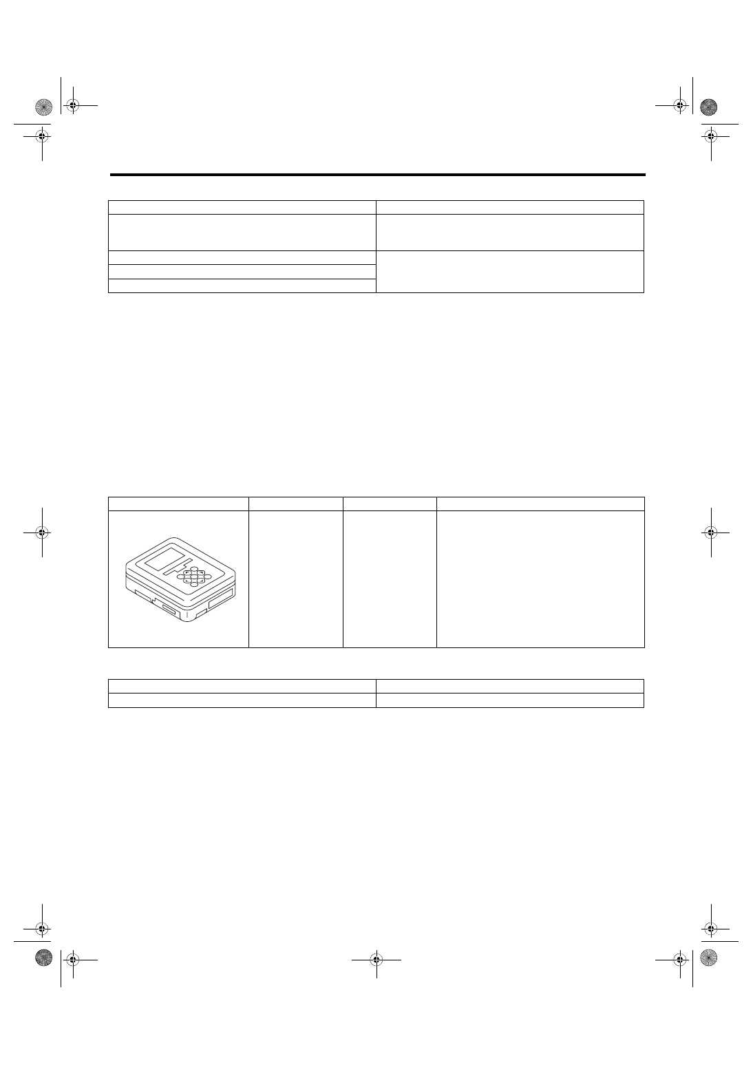
C: PREPARATION TOOL
1. SPECIAL TOOL
2. GENERAL TOOL
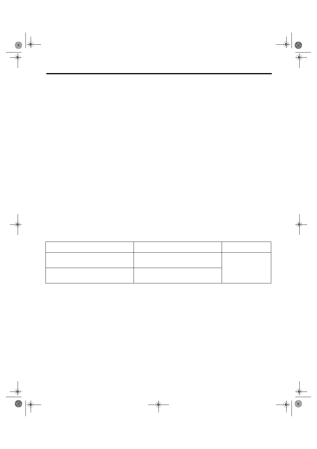
Display
Display method
Average fuel economy/instantaneous fuel economy (except for
U4 model), average fuel economy/blank display (U4 model),
ambient temperature, current time, trouble warning light
VFD
Passenger’s airbag ON indicator
LED
Passenger’s airbag OFF indicator
Passenger’ seat belt warning light
ILLUSTRATION
TOOL NUMBER
DESCRIPTION
REMARKS
1B022XU0
SUBARU SELECT
MONITOR III KIT
Used for troubleshooting the electrical system.
TOOL NAME
REMARKS
Circuit tester
Used for measuring resistance and voltage.
ST1B022XU0
IDI-5
Combination Meter System
INSTRUMENTATION/DRIVER INFO
2. Combination Meter System
A: WIRING DIAGRAM
Refer to “Combination Meter System” in WI section. <Ref. to WI-136, WIRING DIAGRAM, Combination
B: INSPECTION
1. SELF-DIAGNOSIS
The self-diagnosis (checking of each meter, warning light, indicator light, illumination, LCD) of combination
meter can be performed in the following procedure.
CAUTION:
Perform the steps described in 2) through 4) within 10 seconds.
1) Within 3 seconds after turning the ignition switch to ON, set the lighting switch to tail light or headlight po-
sition.
2) Press the odo/trip meter knob three times.
3) Turn the lighting switch to OFF, and press the odo/trip meter knob three times.
4) Set the lighting switch to tail light or headlight position again, and press the odo/trip meter knob three
times.
NOTE:
12, DTC DISPLAY MODE, INSPECTION, Combination Meter System.>
• Warning light, indicator light, and LCD display checks are performed when self-diagnosis is performed. Af-
ter this, every time the odo/trip meter knob is pressed, the buzzer will sound for 0.5 seconds, and operation
checks for meter operation, meter readings, and the LCD are performed in this order. Turn the ignition switch
to OFF to cancel the self-diagnosis function.
• The self-diagnosis function is not canceled if the engine is started during diagnosis. However, the self-di-
agnosis function is canceled automatically for safety when you start to drive the vehicle.
5) Go to “Check meter indicator operation”.
Check meter operation, warning light, indicator light, and LCD.
SPECIFICATION, General Description.>
control. <Ref. to IDI-2, SPECIFICATION, General Description.>
*3
: VDC multi mode indicator light (VDC warning light/VDC indicator light and VDC OFF indicator light) illu-
minates in yellow. (STI model)
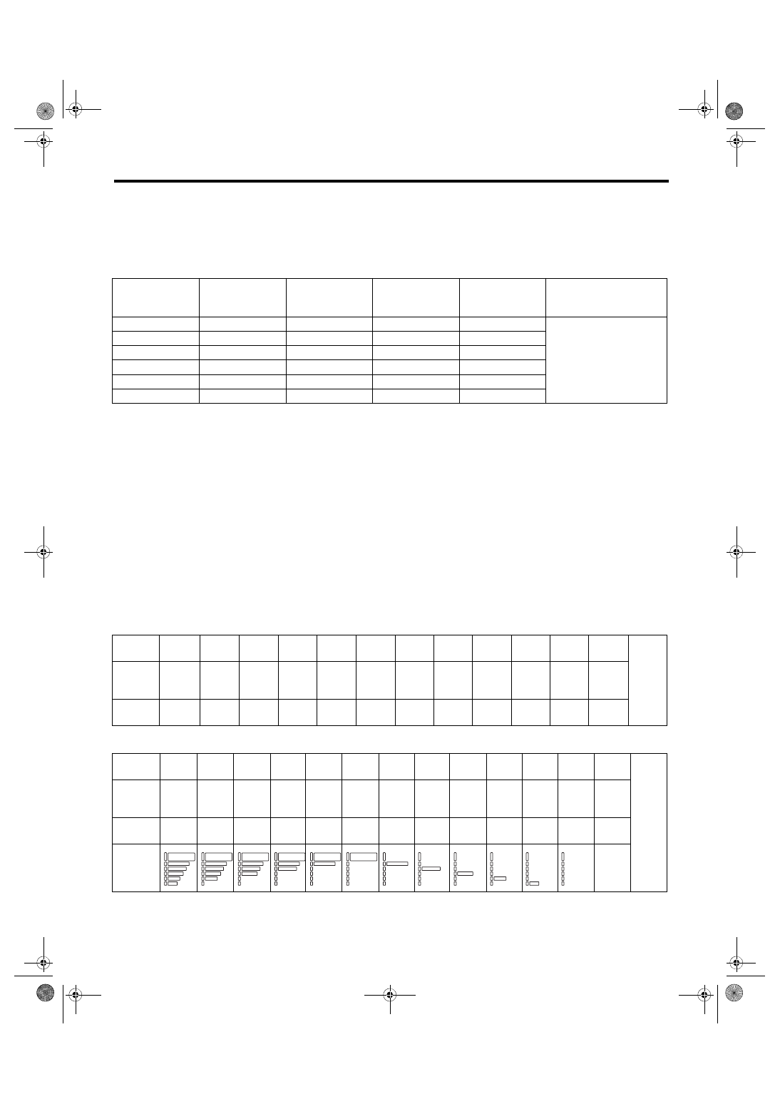
6) Press the odo/trip meter knob once.
Meter indicator
LCD display, illumination
Warning light,
indicator light
MIN indication
↓
MAX indication
ILL1 (Min. brightness)
↓(Display for one second for each level)
ILL6 (Max. brightness)
*1, *2, *3
MAX indication
↓
MIN indication
ILL6 (Max. brightness)
↓(Display for one second for each level)
ILL1 (Min. brightness)
IDI-6
Combination Meter System
INSTRUMENTATION/DRIVER INFO
7) Go to “Meter Indicator Needle Indication Check”.
Check meter operation, warning light, indicator light, and LCD.
NOTE:
• The meter indicator needle will switch every 1.5 seconds.
• ILL indication illuminates at the same brightness as when entering “Meter Indicator Needle Indication
Check”.
control. <Ref. to IDI-2, SPECIFICATION, General Description.>
*3
: VDC multi mode indicator light (VDC traction indicator light) illuminates to green. (STI model)
8) Press the odo/trip meter knob once.
9) Go to “Check LCD display”.
Check the LCD.
NOTE:
control. <Ref. to IDI-2, SPECIFICATION, General Description.>
• The meter indication remains at the same level as “Meter Indicator Needle Indication Check”.
• ILL indication illuminates at ILL6 level (max. brightness).
• Except for STI model
• STI model
Speedometer
(km/h)
Tachometer
(rpm)
Fuel gauge
Engine coolant
temperature
gauge
Fuel level warn-
ing light
Warning light,
indicator light
0
0
Lowest point
Lowest point
Light ON
*1, *2, *3
0
0
E
C
Light ON
40
1000
1/2
1/2
Light OFF
100
4000
F
H
Light OFF
40
1000
1/2
1/2
Light OFF
0
0
E
C
Light ON
Illuminat-
ing order
1
2
3
4
5
6
7
8
9
10
11
12
Go
back to
1 and
repeat.
ODO,
TRIP
A/B
All
lights
ON
All
lights
OFF
ODO
All
lights
OFF
TRIP A
All
lights
OFF
TRIP
B
All
lights
OFF
REV.
All
lights
OFF
TRIP
A
All
lights
OFF
Odo/trip
meter
88888.8 111111 22222.2 333333 44444.4 555555 66666.6 777777 88888.8 999999 00000.0 888888
Illuminat-
ing order
1
2
3
4
5
6
7
8
9
10
11
12
13
Go
back to
1 and
repeat.
ODO,
TRIP
A/B, REV.
All
lights
ON
All
lights
OFF
ODO
All
lights
OFF
TRIP
A
All
lights
OFF
TRIP
B
All
lights
OFF
REV.
All
lights
OFF
TRIP
A
All
lights
OFF
TRIP
B
Odo/trip
meter
88888.8 111111 22222.2 333333 44444.4 555555 66666.6 777777 88888.8 999999 00000.0 888888 88888.8
DCCD
torque
indicator
All
lights
OFF
L O C K
L O C K
L O C K
L O C K
L O C K
L O C K
Нет комментариевНе стесняйтесь поделиться с нами вашим ценным мнением.
Текст