Subaru Impreza 3 / Impreza WRX / Impreza WRX STI. Service manual — part 704
IDI-7
Combination Meter System
INSTRUMENTATION/DRIVER INFO
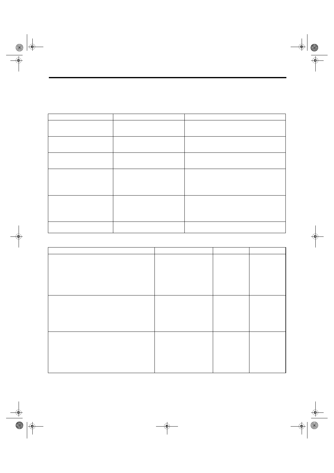
2. SYMPTOM CHART
CAUTION:
When measuring the voltage and resistance of each control module or sensor, use a tapered pin with
a diameter of less than 0.64 mm (0.025 in) in order to avoid poor contact. Do not insert the pin more
than 2 mm (0.08 in).
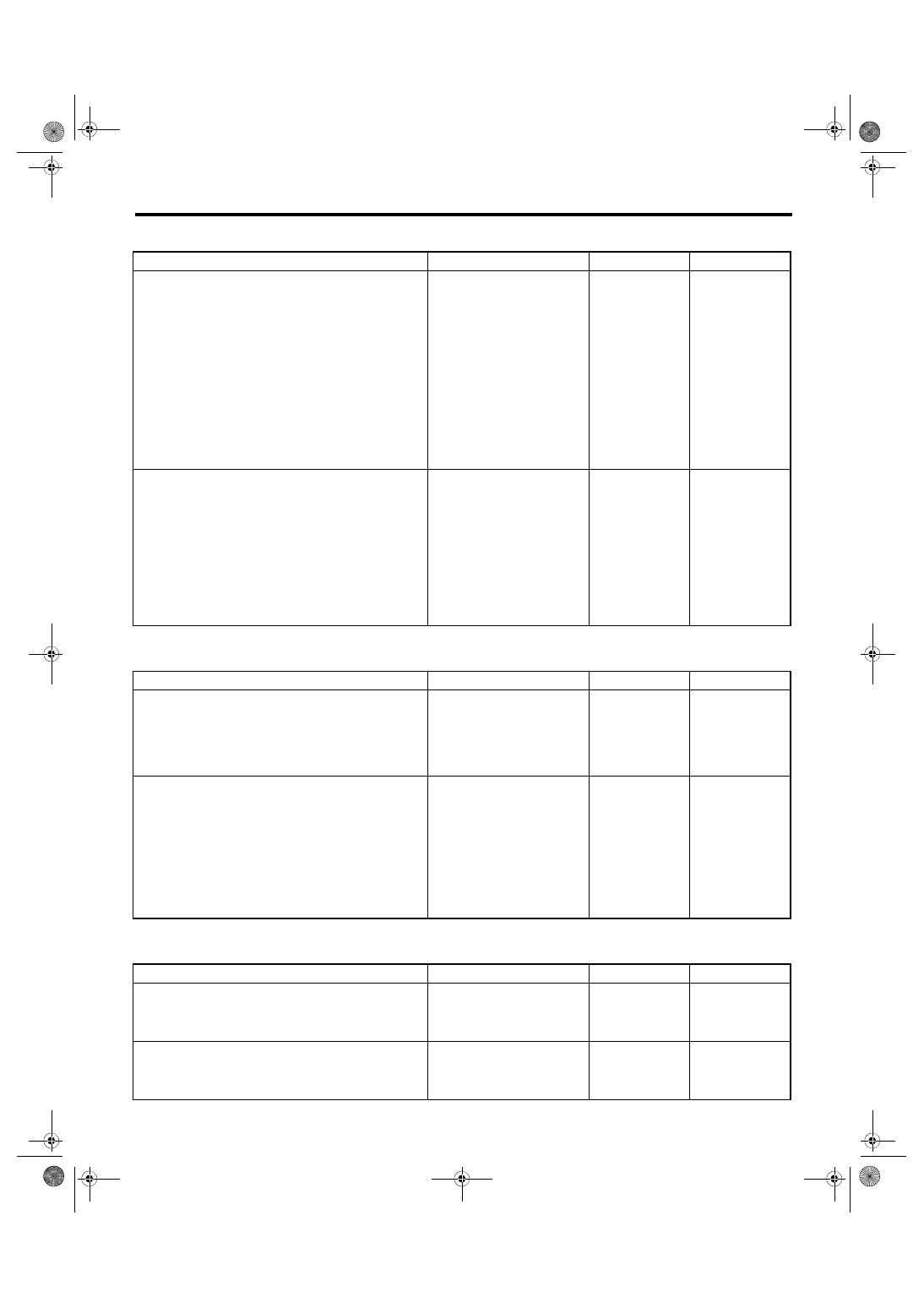
3. CHECK POWER SUPPLY AND GROUND CIRCUIT
Symptoms
Repair order
Note
Combination meter assembly
does not operate.
1. Power supply
2. Ground circuit
3. Combination meter
<Ref. to IDI-7, CHECK POWER SUPPLY AND
GROUND CIRCUIT, INSPECTION, Combination
Meter System.>
Speedometer does not operate.
1. VDC C/M
2. Harness
3. Combination meter
<Ref. to IDI-8, CHECK VDC CONTROL MODULE,
INSPECTION, Combination Meter System.>
Tachometer does not operate.
1. ECM
2. Harness
3. Combination meter
<Ref. to IDI-8, CHECK ENGINE CONTROL MODULE
(ECM), INSPECTION, Combination Meter System.>
Fuel gauge does not operate.
1. Communication circuit
2. Harness
3. Body integrated unit
4. Fuel level sensor
5. Combination meter
<Ref. to IDI-8, CHECK FUEL LEVEL SENSOR,
INSPECTION, Combination Meter System.>
Engine coolant temperature
gauge does not operate.
1. Communication circuit
2. Engine coolant temperature sen-
sor
3. Harness
4. Combination meter
<Ref. to IDI-10, CHECK ENGINE COOLANT TEM-
PERATURE SENSOR, INSPECTION, Combination
Meter System.>
Warning buzzer for key left in igni-
tion does not sound.
1. Communication circuit
2. Combination meter
<Ref. to IDI-11, CHECK KEY WARNING SWITCH
ALARM, INSPECTION, Combination Meter System.>
Step
Check
Yes
No
1
CHECK POWER SUPPLY FOR COMBINA-
TION METER.
1) Remove the combination meter. <Ref. to
IDI-16, REMOVAL, Combination Meter.>
2) Measure the voltage between combination
meter connector and chassis ground.
Connector & terminal
(i10) No. 1 (+) — Chassis ground (–):
Is the voltage 10 V or more?
Check the harness
for open or short
between the fuse
and combination
meter.
2
CHECK POWER SUPPLY FOR COMBINA-
TION METER.
1) Turn the ignition switch to ON.
2) Measure the voltage between combination
meter connector and chassis ground.
Connector & terminal
(i10) No. 2 (+) — Chassis ground (–):
Is the voltage 10 V or more?
Check the harness
for open or short
between the igni-
tion switch and
combination meter.
3
CHECK GROUND CIRCUIT OF COMBINA-
TION METER.
1) Turn the ignition switch to OFF.
2) Measure the resistance of harness between
combination meter connector and body ground.
Connector & terminal
(i10) No. 21 — Chassis ground:
(i10) No. 22 — Chassis ground:
Is the resistance less than 10
Ω?
Replace the meter
case assembly.
Repair or replace
the harness.
IDI-8
Combination Meter System
INSTRUMENTATION/DRIVER INFO
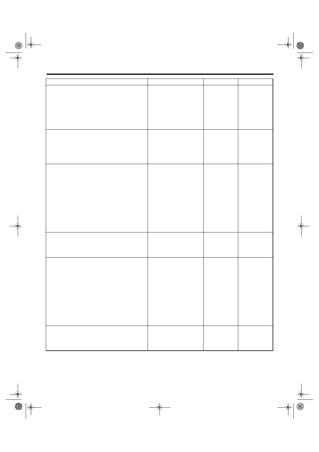
4. CHECK VDC CONTROL MODULE
5. CHECK ENGINE CONTROL MODULE (ECM)
6. CHECK FUEL LEVEL SENSOR
Step
Check
Yes
No
1
CHECK VEHICLE SPEED SIGNAL.
1) Remove the combination meter mounting
screws.
2) Lift up the vehicle and support it with rigid
racks.
3) Drive the vehicle faster than 10 km/h (6
MPH).
WARNING:
Be careful not to get caught in the running
wheels.
4) Measure the voltage between combination
meter connector and chassis ground.
Connector & terminal
(i10) No. 31 (+) — Chassis ground (–):
Is the voltage less than 1 V ←→
5 V or more?
Replace the meter
case assembly.
2
CHECK HARNESS BETWEEN VDC CON-
TROL MODULE AND COMBINATION
METER.
1) Turn the ignition switch to OFF.
2) Disconnect the VDC control unit connector
and the combination meter connector.
3) Measure the resistance between the VDC
control module connector and the combination
meter connector.
Connector & terminal
(B310) No. 33 — (i10) No. 31:
Is the resistance less than 10
Ω?
Check VDC control
module. <Ref. to
VDC(diag)-2,
Basic Diagnostic
Procedure.>
Repair or replace
the harness.
Step
Check
Yes
No
1
CHECK ECM SIGNAL.
1) Start the engine.
2) Measure the voltage between ECM connec-
tor and chassis ground.
Connector & terminal
(B135) No. 15 (+) — Chassis ground (–):
Is the voltage 0 ←→ 14 V or
more?
Inspect the ECM.
<Ref. to
EN(H4DOTC)(diag)
-2, Basic Diagnostic
Procedure.>
2
CHECK HARNESS BETWEEN COMBINA-
TION METER AND ECM.
1) Turn the ignition switch to OFF.
2) Disconnect the ECM connector and combi-
nation meter connector.
3) Measure the resistance between the ECM
connector and the combination meter connec-
tor.
Connector & terminal
(B135) No. 15 — (i10) No. 32:
Is the resistance less than 10
Ω?
Replace the meter
case assembly.
Repair or replace
the harness.
Step
Check
Yes
No
1
CHECK COMBINATION METER.
1) Drain fuel.
2) Check the indication status of the fuel gauge
in the combination meter.
Does the fuel gauge needle
indicate EMPTY and is the low
fuel warning light blinking?
2
CHECK COMBINATION METER.
Perform the self-diagnosis of combination
meter. <Ref. to IDI-5, SELF-DIAGNOSIS,
INSPECTION, Combination Meter System.>
Is it operating normally?
Replace the meter
case assembly.
IDI-9
Combination Meter System
INSTRUMENTATION/DRIVER INFO
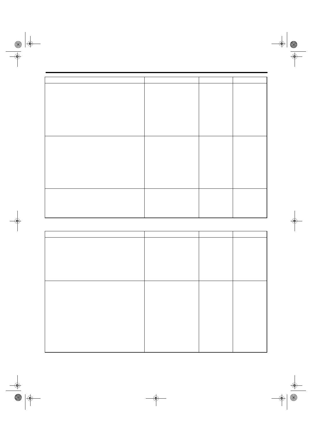
3
CHECK DIAGNOSTIC TROUBLE CODE
(DTC).
1) Prepare the Subaru Select Monitor kit.
2) Turn the ignition switch to ON (engine OFF)
and run the “PC application for Subaru Select
Monitor”.
3) On «System Selection Menu» display,
select {Integ. unit mode}.
4) Select the {Diagnostic Code(s) Display}.
Is DTC being displayed?
4
CHECK HARNESS.
1) Disconnect the body integrated unit connec-
tor.
2) Measure the resistance between body inte-
grated unit connector and chassis ground.
Connector & terminal
(B281) No. 7 — Chassis ground:
Is the resistance 2 — 96 Ω?
If the step 1 is
“Yes”, Go to step
Repair or replace
the harness.
5
CHECK COMMUNICATION BETWEEN
BODY INTEGRATED UNIT AND COMBINA-
TION METERS.
1) Remove the fuel sub level sensor.
• Except for STI model: <Ref. to FU(w/o STI)-
81, REMOVAL, Fuel Sub Level Sensor.>
• STI model: <Ref. to FU(STI)-83, REMOVAL,
Fuel Sub Level Sensor.>
2) Short the fuel sub level sensor connector
terminal to the chassis ground with approx. 100
Ω resistance.
3) Turn the ignition switch to ON.
Connector & terminal
(R59) No. 1 — Chassis ground:
Does the meter needle indicate
EMPTY?
6
CHECK BODY INTEGRATED UNIT.
1) Retain the condition in step 5.
2) On {Integ. unit mode}, select {Fuel level
resistance} using the Subaru Select Monitor.
Is the resistance displayed as
approx. 100 Ω?
Replace the body
integrated unit.
<Ref. to SL-48,
Body Integrated
Unit.>
7
CHECK COMMUNICATION BETWEEN
BODY INTEGRATED UNIT AND COMBINA-
TION METERS.
1) Remove the fuel sub level sensor.
• Except for STI model: <Ref. to FU(w/o STI)-
81, REMOVAL, Fuel Sub Level Sensor.>
• STI model: <Ref. to FU(STI)-83, REMOVAL,
Fuel Sub Level Sensor.>
2) Short the fuel sub level sensor connector
terminal to the chassis ground with approx. 2 Ω
to 6 Ω resistance.
3) Turn the ignition switch to ON.
Connector & terminal
(R59) No. 1 — Chassis ground:
Does the meter needle indicate
FULL?
8
CHECK BODY INTEGRATED UNIT.
1) Retain the condition in step 7.
2) On {Integ. unit mode}, select {Fuel level
resistance} using the Subaru Select Monitor.
Is the resistance 2 — 6 Ω?
Replace the body
integrated unit.
<Ref. to SL-48,
Body Integrated
Unit.>
Step
Check
Yes
No
IDI-10
Combination Meter System
INSTRUMENTATION/DRIVER INFO
7. CHECK ENGINE COOLANT TEMPERATURE SENSOR
9
CHECK FUEL SUB LEVEL SENSOR.
1) Remove the fuel sub level sensor.
• Except for STI model: <Ref. to FU(w/o STI)-
81, REMOVAL, Fuel Sub Level Sensor.>
• STI model: <Ref. to FU(STI)-83, REMOVAL,
Fuel Sub Level Sensor.>
2) Measure the resistance between the fuel
sub level sensor connector terminals when the
float is in FULL and EMPTY position.
Connector & terminal
(R59) No. 1 — No. 2:
Is the resistance 1.0 to 2.5 Ω
(FULL) and 61 to 63 Ω
(EMPTY)?
Replace the fuel
sub level sensor.
10
CHECK FUEL LEVEL SENSOR.
1) Remove the fuel level sensor.
• Except for STI model: <Ref. to FU(w/o STI)-
80, REMOVAL, Fuel Level Sensor.>
• STI model: <Ref. to FU(STI)-82, REMOVAL,
Fuel Level Sensor.>
2) Measure the resistance between the fuel
level sensor connector terminals when the float
is in FULL and EMPTY position.
Connector & terminal
(R58) No. 1 — No. 4:
Is the resistance 1.0 to 3.0 Ω
(FULL) and 31 to 33 Ω
(EMPTY)?
Check the connec-
tion status of the
harness and con-
nector that may
have a temporary
poor contact.
Replace the fuel
level sensor.
11
CHECK COMBINATION METER OPERA-
TION.
1) Remove the combination meter.
2) Attach the combination meter to another
vehicle on which the fuel gauge operates nor-
mally to check its operation.
Is the fuel gauge normal?
Replace the body
integrated unit.
<Ref. to SL-48,
Body Integrated
Unit.>
Replace the meter
case assembly.
Step
Check
Yes
No
1
CHECK DIAGNOSTIC TROUBLE CODE
(DTC).
1) Prepare the Subaru Select Monitor kit.
2) Turn the ignition switch to ON (engine OFF)
and run the “PC application for Subaru Select
Monitor”.
3) On «System Selection Menu» display,
select {Integ. unit mode}.
4) Select {Diagnostic Code(s) Display}.
Is DTC being displayed?
2
CHECK ENGINE COOLANT TEMPERATURE
SENSOR.
Check the engine coolant temperature sensor.
<Ref. to EN(H4DOTC)(diag)-2, Basic Diagnos-
tic Procedure.>
Is the engine coolant tempera-
ture sensor OK?
Replace the meter
case assembly.
Replace the
engine coolant
temperature sen-
sor.
• Except for STI
model: <Ref. to
FU(w/o STI)-34,
REMOVAL, Engine
Coolant Tempera-
ture Sensor.>
• STI model: <Ref.
to FU(STI)-34,
REMOVAL, Engine
Coolant Tempera-
ture Sensor.>
Step
Check
Yes
No
Нет комментариевНе стесняйтесь поделиться с нами вашим ценным мнением.
Текст