Subaru Impreza 3 / Impreza WRX / Impreza WRX STI. Service manual — part 51
EC(STI)-18
Shut Valve
EMISSION CONTROL (AUX. EMISSION CONTROL DEVICES)
10.Shut Valve
A: REMOVAL
WARNING:
Place “NO OPEN FLAMES” signs near the
working area.
CAUTION:
Be careful not to spill fuel.
1) Remove the fuel filler pipe. <Ref. to FU(STI)-77,
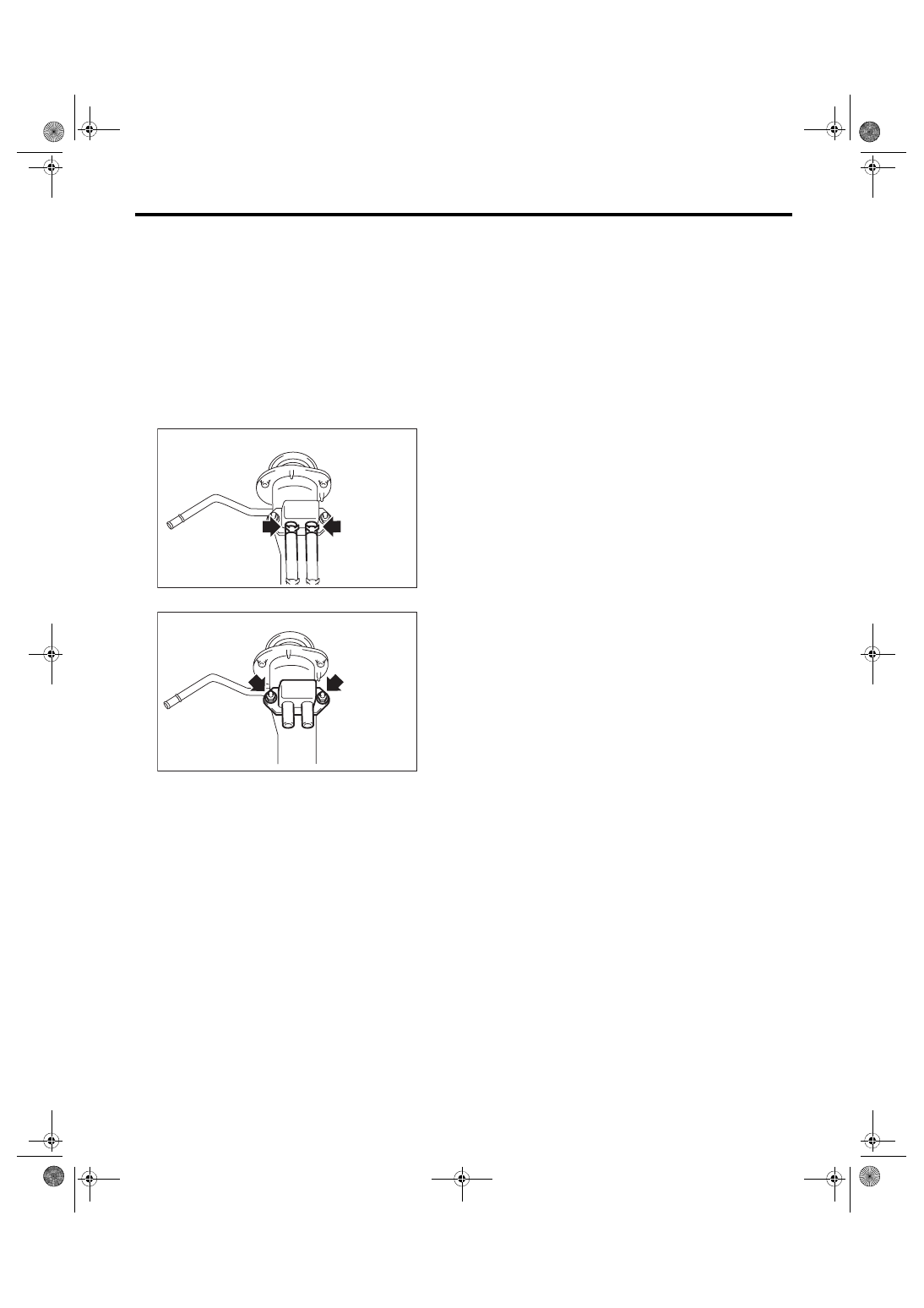
2) Disconnect the evaporation hose from the shut
valve.
3) Remove the shut valve from the fuel filler pipe.
B: INSTALLATION
Install in the reverse order of removal.
Tightening torque:
4.5 N·m (0.5 kgf-m, 3.3 ft-lb)
C: INSPECTION
1) Check that the shut valve has no deformation,
cracks or other damages.
2) Check that the evaporation hose has no cracks,
damage or loose part.
EC-02753
EC-02481
EC(STI)-19
Leak Check Valve Assembly
EMISSION CONTROL (AUX. EMISSION CONTROL DEVICES)
11.Leak Check Valve Assembly
A: REMOVAL
Refer to “Canister” for removal procedures. <Ref.
to EC(STI)-7, REMOVAL, Canister.>
B: INSTALLATION
Refer to “Canister” for installation procedures.
<Ref. to EC(STI)-9, INSTALLATION, Canister.>
C: DISASSEMBLY
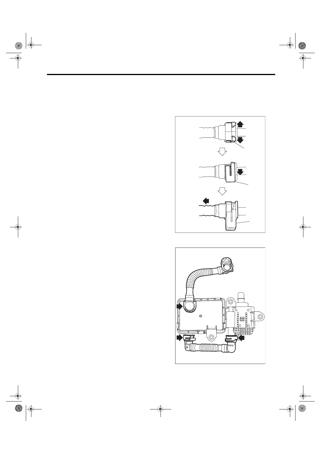
Disconnect the drain tube from the leak check
valve assembly.
NOTE:
Disconnect the quick connector as shown in the fig-
ure.
(a) Retainer
EC-02281
(a)
(a)
(a)
EC-02988
EC(STI)-20
Leak Check Valve Assembly
EMISSION CONTROL (AUX. EMISSION CONTROL DEVICES)
D: ASSEMBLY
Assemble the parts in the reverse order of disas-
sembly while being careful of the following.
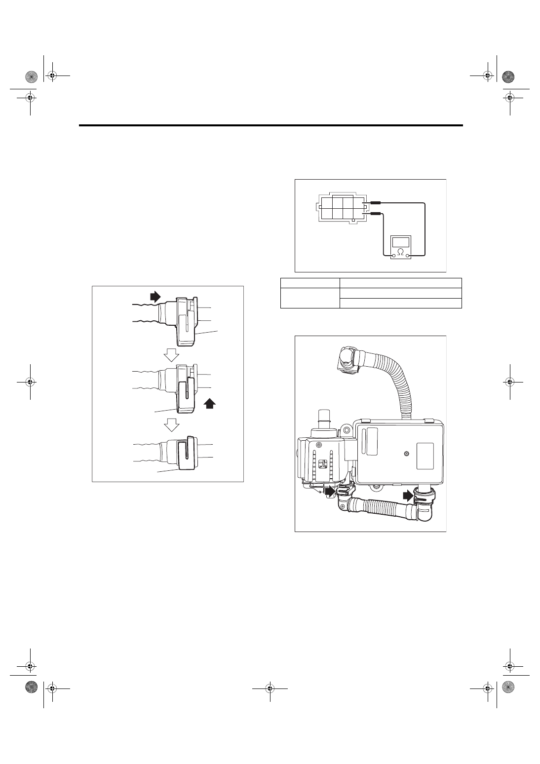
• Connect the quick connector as shown in the fig-
ure.
CAUTION:
• Check that there is no damage or dust on the
quick connector. If necessary, clean the seal
surface of the pipe.
• When connecting the quick connector, se-
curely insert the pipe all the way before locking
the retainer.
• When it is difficult to lock the retainer, make
sure that the pipe is securely inserted.
• Make sure that the quick connector is secure-
ly connected.
E: INSPECTION
1. CHECK SWITCHING VALVE
1) Check the resistance between switching valve
terminals.
2) Disconnect the drain tube from the leak check
valve assembly.
(a) Retainer
EC-02295
(a)
(a)
(a)
Terminal No.
Standard
1 and 5
27
+3
–2
Ω (when 20°C (68°F))
31±4 Ω (when 60°C (140°F))
EC-02989
4 3
1
8 7 6 5
2
EC-02990
EC(STI)-21
Leak Check Valve Assembly
EMISSION CONTROL (AUX. EMISSION CONTROL DEVICES)
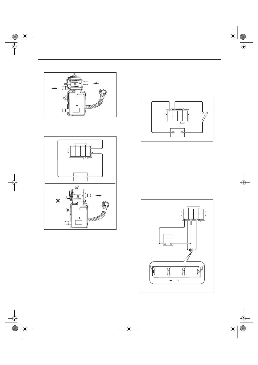
3) Check that air is discharged from (B) when air is
blown into (A).
4) Connect the battery positive terminal to the ter-
minal No. 5 and the battery negative terminal to the
terminal No. 1. Check that air does not come out
from (B) when air is blown into (A).
2. CHECK VACUUM PUMP
1) Connect the battery positive terminal to terminal
No. 3 and the battery ground terminal to terminal
No. 4, and inspect the vacuum pump operation.
CAUTION:
Do not operate the vacuum pump for 5 minutes
or more.
3. CHECK PRESSURE SENSOR
1) Connect dry-cell battery positive terminal to ter-
minal No. 6 and dry-cell battery ground terminal to
terminal No. 8, circuit tester positive terminal to ter-
minal No. 7 and the circuit tester negative terminal
to terminal No. 8.
NOTE:
• Use new dry-cell batteries.
• Using circuit tester, check the voltage of a single
dry-cell battery is 1.6 V or more. And also check the
voltage of three batteries in series is between 4.8 V
and 5.2 V.
EC-03405
(A)
(B)
EC-03406
(A)
(B)
4 3
1
8 7 6 5
2
EC-02993
4 3
1
8 7 6 5
2
EC-02994
4.8 5.2V
1.5V
1.5V
1.5V
4 3
1
8 7 6 5
2
V
Нет комментариевНе стесняйтесь поделиться с нами вашим ценным мнением.
Текст