Subaru Impreza 3 / Impreza WRX / Impreza WRX STI. Service manual — part 52
EC(STI)-22
Leak Check Valve Assembly
EMISSION CONTROL (AUX. EMISSION CONTROL DEVICES)
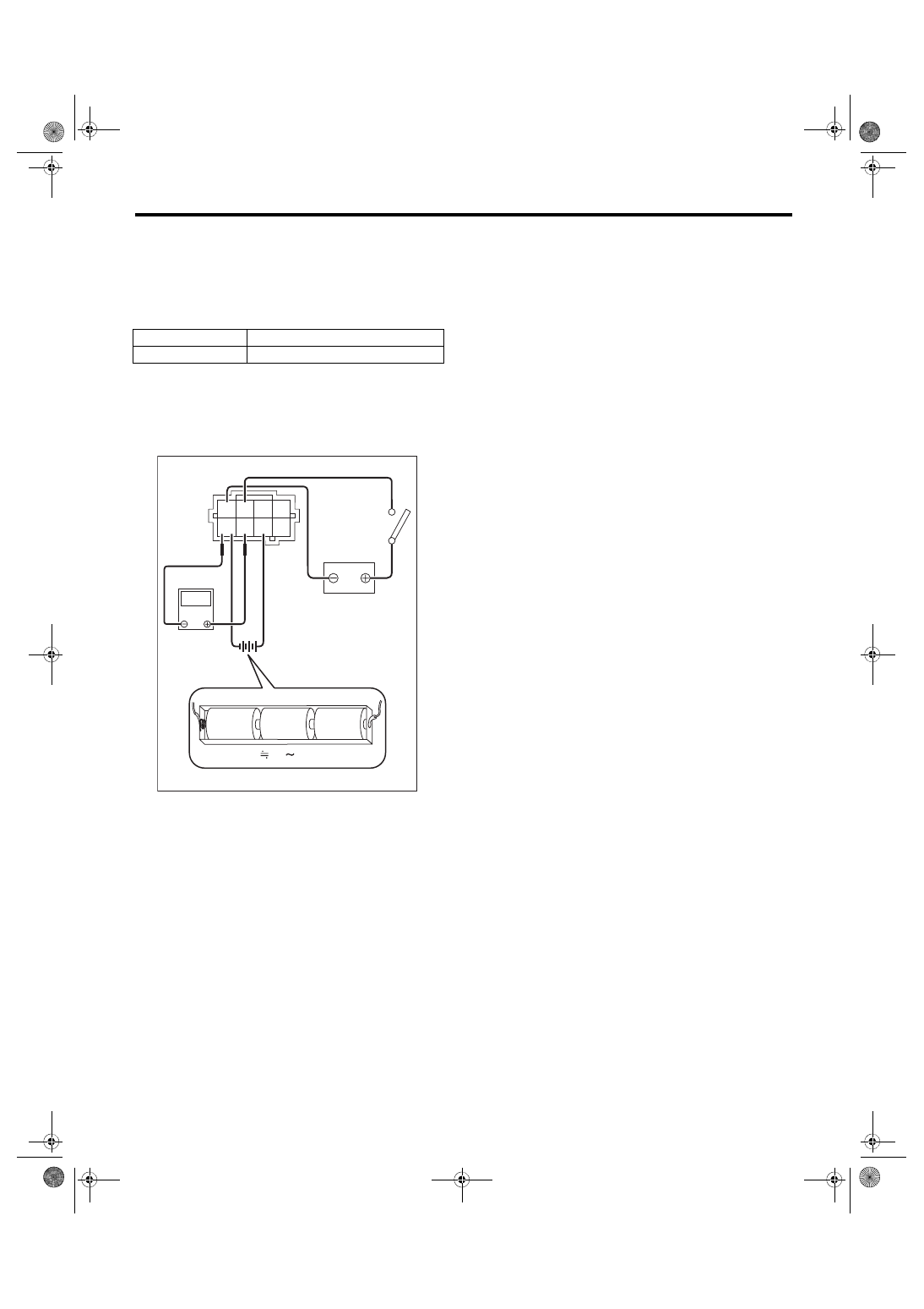
2) Check the voltage at a normal atmospheric pres-
sure.
NOTE:
The atmospheric pressure at higher altitude is low-
er than normal. Therefore, the voltage is lower than
the standard value.
3) Connect the battery positive terminal to terminal
No. 3 and the battery ground terminal to terminal
No. 4, and check that there is a voltage drop from
the voltage measured in step 2) when the vacuum
pump is operated.
4. OTHER INSPECTIONS
Check that the drain tube has no cracks, damage
or loose part.
Terminal No.
Standard
7 (+) and 8 (–)
Approx. 3.5 V (when 25°C (77°F))
EC-02995
4.8 5.2V
1.5V
1.5V
1.5V
4 3
1
8 7 6 5
2
V
EC(STI)-23
Drain Separator
EMISSION CONTROL (AUX. EMISSION CONTROL DEVICES)
12.Drain Separator
A: REMOVAL
1) Lift up the vehicle.
2) Remove the rear differential. <Ref. to DI-22, RE-
MOVAL, Rear Differential (T-type).>
3) Disconnect the drain hose from the connector.
4) Remove the drain separator from the vehicle.
B: INSTALLATION
Install in the reverse order of removal.
Tightening torque:
7.5 N·m (0.8 kgf-m, 5.5 ft-lb)
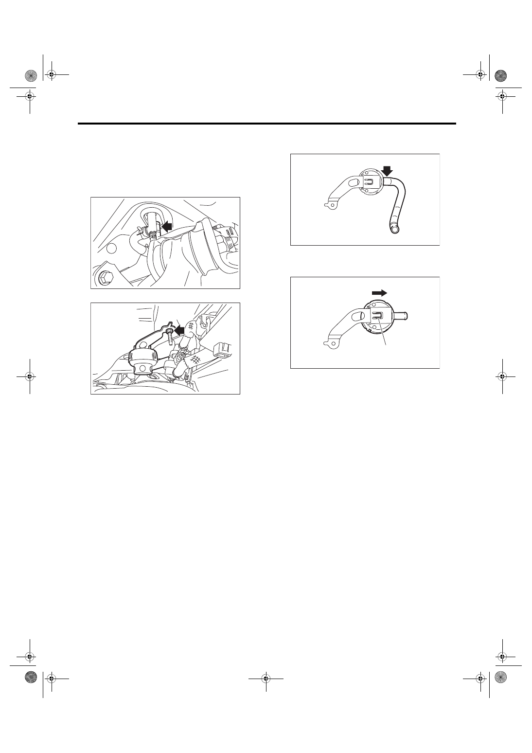
C: DISASSEMBLY
1) Remove the drain hose from the drain separator.
2) Lift up the claw (A) of the drain separator and
slide the drain separator in the direction of the ar-
row to remove the drain separator.
D: ASSEMBLY
Assemble in the reverse order of disassembly.
E: INSPECTION
1) Check that the drain separator and drain separa-
tor bracket have no deformation, crack, or other
damage.
2) Check that the drain hose has no crack, dam-
age, or looseness.
3) Check that no foreign substances are clogged in
the drain separator.
EC-02715
EC-03163
EC-03164
EC-03165
(A)
EC(STI)-24
PCV Hose Assembly
EMISSION CONTROL (AUX. EMISSION CONTROL DEVICES)
13.PCV Hose Assembly
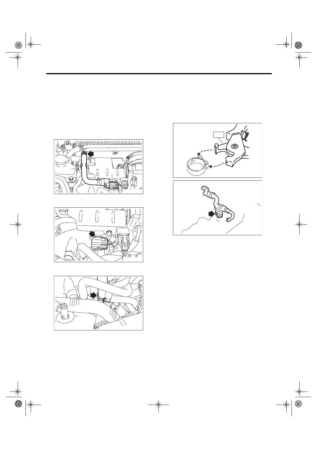
A: REMOVAL
CAUTION:
Do not remove unless the hose and the diag-
nostics connector are broken.
1) Disconnect the connector (A) from the PCV hose
assembly A.
2) Remove the PCV hose assembly A from the clip
(B), and remove the PCV hose assembly A from
the PCV pipe.
3) Remove the connector from the PCV hose as-
sembly B.
4) Remove the PCV hose assembly B from the in-
take duct.
5) Remove the intake manifold. <Ref. to FU(STI)-
17, REMOVAL, Intake Manifold.>
6) Remove the turbocharger. <Ref. to IN(STI)-15,
7) Remove the PCV hose assembly C from the cyl-
inder block RH.
NOTE:
Pinch the clamp of the PCV hose assembly C by fit-
ting the cut out in the ST with the protrusion on the
clamp as shown in the figure, and unlock the
clamp.
ST 18353AA000 CLAMP PLIERS
EC-03007
(B)
(A)
EC-03008
EC-03009
ME-04374
ST
EC-03011
EC(STI)-25
PCV Hose Assembly
EMISSION CONTROL (AUX. EMISSION CONTROL DEVICES)
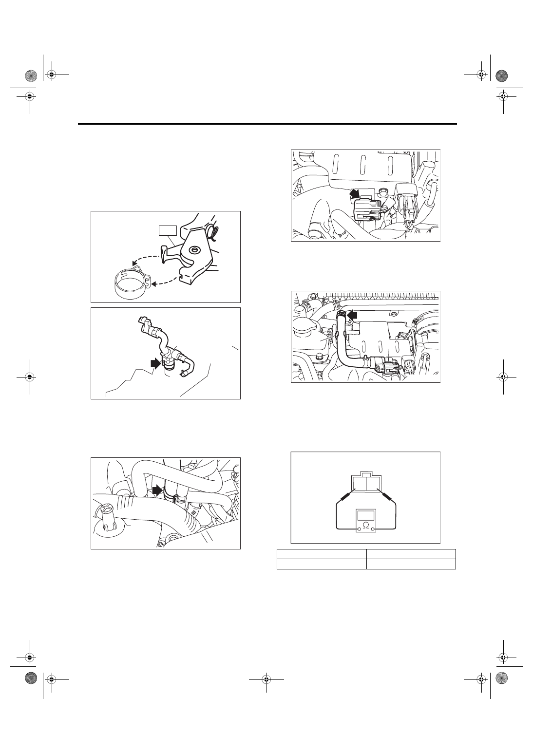
B: INSTALLATION
1) Install the PCV hose assembly C onto the cylin-
der block RH.
NOTE:
Use a new clamp for the PCV hose assembly C, fit
the cut out in the ST with the protrusion on the
clamp as shown in the figure, and lock the clamp.
ST 18353AA000 CLAMP PLIERS
2) Install the turbocharger. <Ref. to IN(STI)-16, IN-
3) Install the intake manifold. <Ref. to FU(STI)-21,
INSTALLATION, Intake Manifold.>
4) Install the PCV hose assembly B onto the intake
duct.
5) Connect the connector to the PCV hose assem-
bly B.
6) Install the PCV hose assembly A to the PCV
pipe, and install the PCV hose assembly A to the
clip (B).
7) Connect the connector (A) to the PCV hose as-
sembly A.
C: INSPECTION
1. DIAGNOSIS CONNECTOR
1) Check that the diagnosis connector has no de-
formation, cracks and any other damage.
2) Check the resistance between the diagnosis
connector terminals.
2. OTHER INSPECTIONS
1) Check that the PCV connector has no deforma-
tion, cracks or other damages.
2) Check that the hose has no cracks, damage or
loose part.
ME-04374
ST
EC-03011
EC-03009
Terminal No.
Standard
1 and 2
Less than 1 Ω
EC-03008
EC-03007
(B)
(A)
2 1
EC-02428
Нет комментариевНе стесняйтесь поделиться с нами вашим ценным мнением.
Текст