Subaru Impreza 3 / Impreza WRX / Impreza WRX STI. Service manual — part 580
PS-41
Pipe Assembly
POWER ASSISTED SYSTEM (POWER STEERING)
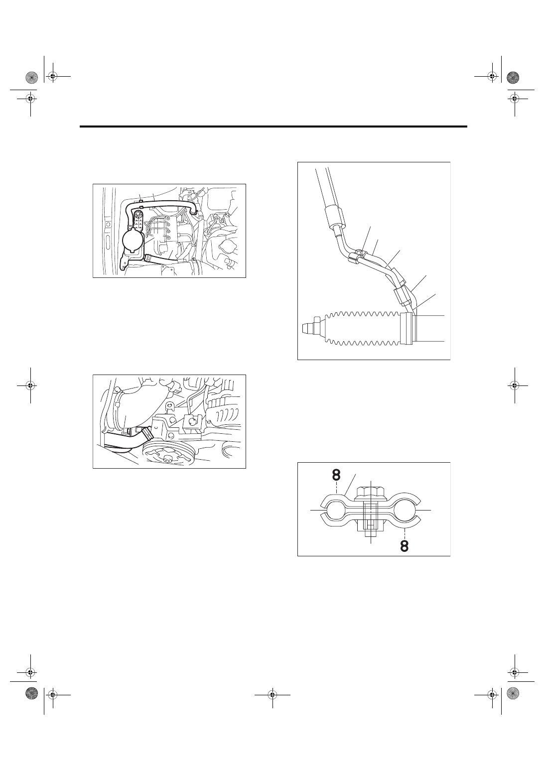
3) Connect the suction hose and return hose to the
reservoir tank.
CAUTION:
Firmly insert the plastic clip of return hose to
the bracket.
4) Connect the suction hose and pressure hose to
the oil pump. Tighten the eyebolt of pressure hose.
Tightening torque:
40 N·m (4.1 kgf-m, 29.5 ft-lb)
5) Temporarily connect the pressure hose to feed
pipe and return hose to return pipe. Temporarily
tighten the bolt of clamp E.
NOTE:
Make sure that the character “8” on each clamp is
positioned on the opposite side, as shown in the
figure.
(1) Reservoir tank
(2) Suction hose
(3) Return hose
(4) Plastic clip
(1) Suction hose
(2) Pressure hose
PS-01212
(3)
(1)
(2)
(4)
PS-00459
(2)
(1)
(1) Return hose
(2) Pressure hose
(3) Clamp E
(4) Return pipe
(5) Feed pipe
(1) Clamp E
(2) Pressure hose
(3) Return hose
PS-00847
(3)
(2)
(4)
(5)
(1)
PS-01344
(2)
(1)
(3)
PS-42
Pipe Assembly
POWER ASSISTED SYSTEM (POWER STEERING)
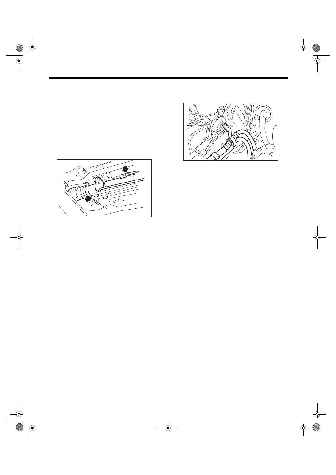
6) Tighten clamp E.
Tightening torque:
7.5 N·m (0.76 kgf-m, 5.5 ft-lb)
7) Tighten the pressure hose to feed pipe and re-
turn hose to return pipe.
Tightening torque:
15 N·m (1.5 kgf-m, 11.1 ft-lb)
8) Connect pipes A and B to the four pipe joints of
the gearbox.
Tightening torque:
Cylinder side: 27 N·m (2.8 kgf-m, 19.9 ft-lb)
Gear housing side: 17 N·m (1.7 kgf-m, 12.5 ft-lb)
9) Install the front crossmember support plate and
jack-up plate.
10) Install the under cover. <Ref. to EI-28, INSTAL-
11) Lower the vehicle.
12) Tighten the bolts which hold the hose bracket.
Tightening torque:
10 N·m (1.0 kgf-m, 7.4 ft-lb)
13) Install the air intake duct.
• Except for STI model: <Ref. to IN(w/o STI)-10,
INSTALLATION, Air Intake Duct.>
• STI model: <Ref. to IN(STI)-10, INSTALLATION,
14) Connect the battery ground terminal.
15) Fill with the specified fluid.
CAUTION:
Never start the engine before filling with fluid;
otherwise the vane pump may become seized.
16) Finally, check the clearance between pipes or
hoses as shown in the figure indicated in “General
Diagnostic Table”. <Ref. to PS-57, INSPECTION
OF CLEARANCE, INSPECTION, General Diag-
(1) Pipe A
(2) Pipe B
(2)
PS-00553
(1)
(1) Hose ASSY
(2) Hose bracket
PS-00624
(2)
(1)
PS-43
Pipe Assembly
POWER ASSISTED SYSTEM (POWER STEERING)
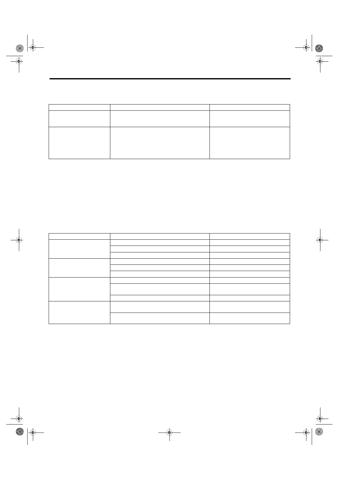
C: INSPECTION
Check all disassembled parts for wear, damage or other problems. Repair or replace the defective parts as
necessary.
CAUTION:
Although the surface layer materials of rubber hoses have excellent weathering resistance, heat re-
sistance and resistance for low temperature brittleness, they are likely to be damaged chemically by
brake fluid, battery electrolyte, engine oil and automatic transmission fluid and their service lives are
to be very shortened. Wipe off hoses immediately if any of these come into contact with the hoses.
Since resistances for heat or low temperature brittleness are gradually declining according to time
accumulation of hot or cold conditions for the hoses and their service lives are shortening accord-
ingly, it is necessary to perform careful inspection frequently when the vehicle is used in hot weather
areas, cold weather areas and a driving condition in which many steering operations are required in
short time.
Continuous discharge of the relief valve for 5 seconds or more will reduce the service lives of hoses,
oil pump, fluid, etc., due to over heating.
Part
Maintenance parts
Corrective action
Pipe
• O-ring fitting surface damage
• Nut damage
• Pipe damage
Replace with a new part.
Hose
• Flare surface damage
• Flare nut damage
• Outer surface cracks
• Outer surface wear
• Clip damage
• End coupling or adapter deformation
Replace with a new part.
Trouble
Possible cause
Corrective action
Pressure hose burst
Excessive holding time of relief status
Instruct customers.
Malfunction of the relief valve
Replace the oil pump.
Poor cold characteristic of fluid
Replace fluid.
Disconnection of the return
hose
Improper connection
Repair.
Loosening of the clip
Replace the hose and clip.
Poor cold characteristic of fluid
Replace fluid.
Fluid slightly leaking out of
hose
Wrong layout, tensioned
Replace the hose.
Excessive play of engine due to deterioration of
engine mounting rubber
Replace the parts if defective.
Improper stop position of pitching stopper
Replace the parts if defective.
Crack on hose
Excessive holding time of relief status
Replace.
Instruct customers.
Power steering fluid, engine oil, electrolyte adhere
on the hose surface
Replace.
Be careful during service work.
PS-44
Pipe Assembly
POWER ASSISTED SYSTEM (POWER STEERING)
NOTE:
There are conditions in which a fluid leak is diagnosed, but is not actually leaking. This is because the fluid
spilt during the last maintenance was not completely wiped off. Be sure to wipe off spilt fluid thoroughly after
maintenance.
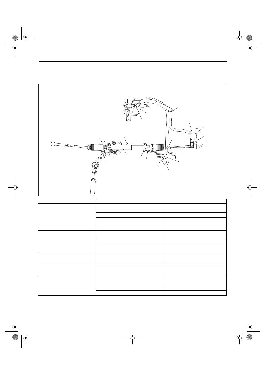
Fluid leaking area
Possible cause
Corrective action
Leakage from the connections of
pipes and hoses, numbered (1)
through (8) in the figure
Insufficient tightening of flare nut, adhesion of
dirt, damage to flare or flare nut or eyebolt
Loosen and retighten. Replace if ineffec-
tive.
Improper installation of hose or clamp
Replace.
Damaged O-ring or gasket
Replace the O-ring, gasket pipe or hose
with new part, if still no improvement,
replace the gearbox or oil pump as well.
Leakage from hose (9) through (13) in
the figure
Crack or damage in hose
Replace with a new part.
Crack or damage in hose hardware
Replace with a new part.
Leakage from surrounding of alumi-
num portion of oil pump, (14) and (15)
in the figure
Damaged O-ring
Replace the oil pump.
Damaged gasket
Replace the oil pump.
Leakage from oil tank, (16) and (17) in
the figure
Crack in oil tank
Replace the oil tank.
Leakage from filler neck of (18)
Damaged cap packing
Replace the cap.
Crack in root of filler neck
Replace the oil tank.
Fluid level too high
Adjust the fluid level.
Leakage from power cylinder of gear-
box area (19) in the figure
Damaged oil seal
Replace the oil seal.
Leakage from (20), (21) in the figure
and control valve of gearbox
Damaged packing or oil seal
Replace the faulty parts.
Damage in control valve
Replace the control valve.
(10)
(17)
(1)
(13)
(19)
(4)
(2)
(9)
(12)
(16)
(18)
(5)
(6)
(20)
(3)
(21)
PS-00883
(11)
(7)
(14)
(15)
(8)
Нет комментариевНе стесняйтесь поделиться с нами вашим ценным мнением.
Текст