Subaru Impreza 3 / Impreza WRX / Impreza WRX STI. Service manual — part 578
PS-33
Steering Gearbox
POWER ASSISTED SYSTEM (POWER STEERING)
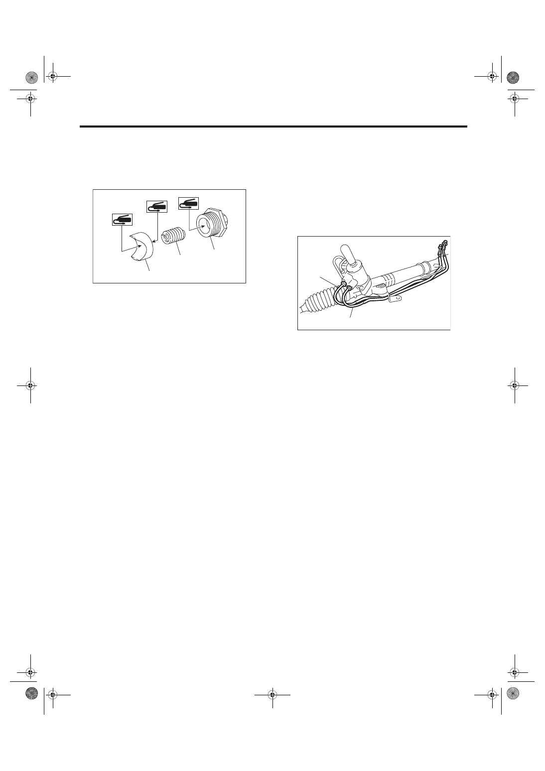
21) Apply a coat of grease to the sliding surface of
sleeve and seating surface of spring, and then in-
sert the sleeve into steering body.
Charge the adjusting screw with grease, and then
insert the spring into adjusting screw. Then install
on the steering body.
22) Tighten the adjusting screw to the specified
torque, then loosen it.
Tightening torque:
25 N·m (2.5 kgf-m, 18.4 ft-lb)
23) Tighten the adjusting screw to the specified
torque, then loosen it within 20°.
Tightening torque:
5.9 N·m (0.6 kgf-m, 4.4 ft-lb)
24) Adjust the turning resistance of gearbox so that
it is within specification using adjusting screw.
<Ref. to PS-36, TURNING RESISTANCE OF
GEARBOX, INSPECTION, Steering Gearbox.>
25) Attach the lock nut into adjusting screw, and
while holding the adjusting screw with wrench,
tighten the lock nut using ST.
ST 926230000
SPANNER
Tightening torque (lock nut):
25 N·m (2.5 kgf-m, 18.4 ft-lb)
NOTE:
Hold the adjusting screw with a wrench to prevent it
from turning while tightening lock nut.
26) Remove the gearbox from ST.
ST1 926200000
STAND
ST2 34199AG000 BOSS D
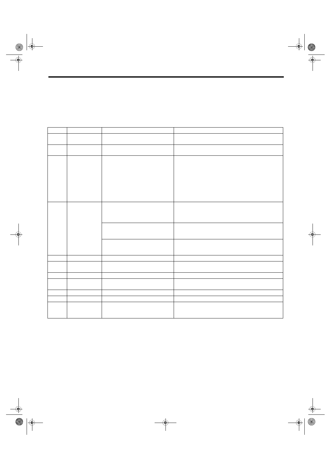
27) Install the four pipes on gearbox.
(1) Connect the pipes A and B to gearbox.
Tightening torque:
Cylinder side: 27 N·m (2.8 kgf-m, 19.9 ft-lb)
Gear housing side: 17 N·m (1.7 kgf-m, 12.5 ft-lb)
(2) Connect the feed pipe and return pipe to the
gearbox.
Tightening torque:
Feed pipe: 37 N·m (3.8 kgf-m, 27.3 ft-lb)
Return pipe: 29 N·m (3.0 kgf-m, 21.4 ft-lb)
(1) Sleeve
(2) Spring
(3) Adjusting screw
(2)
(1)
(3)
PS-00167
(1) Feed pipe
(2) Return pipe
PS-00525
(1)
(2)
PS-34
Steering Gearbox
POWER ASSISTED SYSTEM (POWER STEERING)
E: INSPECTION
1. BASIC INSPECTION
1) Clean all the disassembled parts, and check for wear, damage or any other faults, then repair or replace
as necessary.
2) When disassembling, check the inside of gearbox for water. If any water is found, carefully check the boot
for damage, input shaft dust seal, adjusting screw and boot clips for poor sealing. If faulty, replace with new
parts.
No.
Parts
Inspection
Corrective action
1
Input shaft
(1) Bent input shaft
(2) Damage on serration
If the bend or damage is excessive, replace the entire
gearbox.
2
Dust seal
(1) Crack or damage
(2) Wear
If the outer wall slips, the lip is worn out or damage is
found, replace it with a new part.
3
Rack and pinion
Poor mating of rack with pinion
(1) Adjust the backlash properly.
By measuring the turning torque of the gearbox and sliding
resistance of rack, check if the rack & pinion engage uni-
formly and smoothly with each other. (Refer to “Service
limit”.)
(2) Pull out the entire rack to allow viewing of the teeth, and
check for damage.
Even if abnormality is found in either (1) or (2), replace the
entire gearbox.
4
Gearbox unit
(1) Bending of the rack shaft
(2) Bending of the cylinder portion
(3) Crack or damage on the aluminum
portion
Replace the gearbox with a new part.
(4) Wear or damage on rack bushing
If the free play of rack shaft in radial direction is out of the
specified range, replace the gearbox with new part. (Refer
to “Service limit”.)
(5) Wear on input shaft bearing
If the free play of input shaft in radial and axial direction is
out of the specified range, replace the gearbox with a new
part. (Refer to “Service limit”.)
5
Boot
Crack, damage or deterioration
Replace.
6
Tie-rod
(1) Looseness of ball joint
(2) Bend of tie-rod
Replace.
7
Tie-rod end
Damage or deterioration of dust seal
Replace.
8
Adjusting screw
spring
Deterioration
Replace.
9
Boot clip
Deterioration
Replace.
10
Sleeve
Damage
Replace.
11
Pipe
(1) Damage to flared surface
(2) Damage to flare nut
(3) Damage to pipe
Replace.
PS-35
Steering Gearbox
POWER ASSISTED SYSTEM (POWER STEERING)
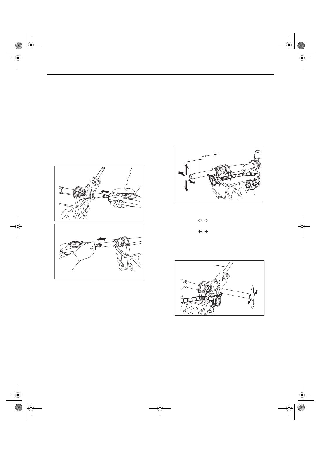
2. SERVICE LIMIT
Make a measurements as follows. If it exceeds the
specified service limits, adjust or replace.
NOTE:
When making a measurement, vise the gearbox
using ST. Never vise the gearbox by inserting alu-
minum plates etc. between vise and gearbox.
ST1 926200000
STAND
ST2 34199AG000 BOSS D
Rack shaft sliding resistance:
Limit
343 N (35 kgf, 77 lbf) or less
Left/right differential of sliding resistance:
20% or less
3. RACK SHAFT PLAY IN THE RADIAL DI-
RECTION
Right-turn steering:
Limit
0.12 mm (0.005 in) or less
Condition
Weighting point
L1: 10 mm (0.39 in)
P: 98 N (10 kgf, 22 lb)
Measuring point
L2: 5 mm (0.2 in)
Left-turn steering:
Limit
Direction
0.3 mm (0.012 in) or less
Direction
0.15 mm (0.0059 in) or less
Condition
L: 5 mm (0.20 in)
P: 98 N (10 kgf, 22 lbf)
PS-00099
PS-00100
PS-01466
P
L2
L1
L
P
PS-00102
PS-36
Steering Gearbox
POWER ASSISTED SYSTEM (POWER STEERING)
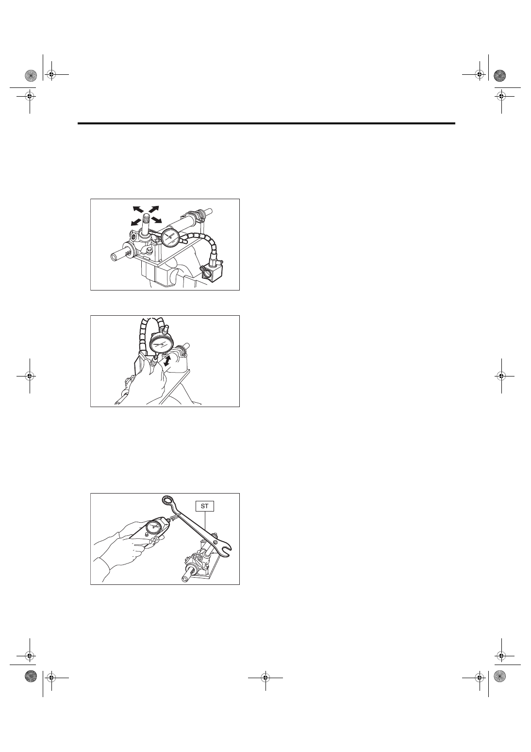
4. INPUT SHAFT PLAY
In radial direction:
Service limit
0.26 mm (0.01 in) or less
Condition
P: 98 N (10 kgf, 22 lb)
In axial direction:
Without play
5. TURNING RESISTANCE OF GEARBOX
Using the ST, measure the gearbox turning resistance.
ST 34099PA100 SPANNER
Service limit:
Maximum allowable resistance:
13.7 N (1.40 kgf, 3.08 lb) or less
Difference between right and left turning resistance:
24% or less
P
PS-00103
PS-00104
P
PS-00105
Нет комментариевНе стесняйтесь поделиться с нами вашим ценным мнением.
Текст