Subaru Impreza 3 / Impreza WRX / Impreza WRX STI. Service manual — part 579
PS-37
Steering Gearbox
POWER ASSISTED SYSTEM (POWER STEERING)
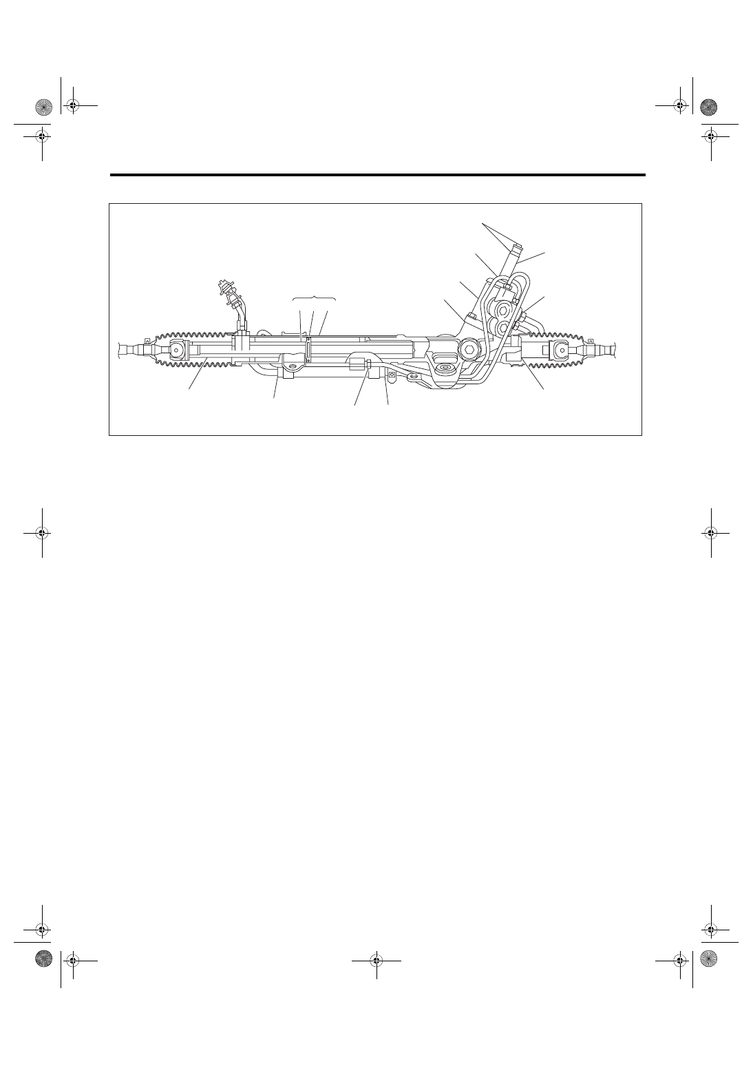
6. FLUID LEAKAGE
1) Lift up the vehicle.
2) If a fluid leak is found, clean the fluid completely
from the suspect area, and turn the steering wheel
30 to 40 times to the left and right from lock to lock,
with the engine running, and check again for leaks
immediately, and also after a few hours have
passed.
3) Cause and solution for oil leakage from “a”
The oil seal is damaged. Replace the valve assem-
bly or valve housing side oil seal assembly with a
new part.
4) Cause and solution for oil leakage from “b”
The torsion bar O-ring is damaged. Replace the
valve assembly with a new part.
5) Cause and solution for oil leakage from “c”
The oil seal is damaged. Replace the valve assem-
bly or pinion side oil seal with a new part.
6) Cause and solution for oil leakage from “d”
The pipe is damaged. Replace the faulty pipe or O-
ring.
7) Cause and solution for oil leakage from “g”
The hose is damaged. Replace the hose with a
new part.
8) If leak is other than a, b, c, d or g, or if oil is leak-
ing from gearbox, move the right and left boots to-
ward tie-rod end side, respectively, with the
gearbox mounted to the vehicle, and remove fluid
from surrounding portions. Then, turn the steering
wheel from lock to lock about 30 to 40 times with
the engine running, then re-inspect the leaking
area immediately after and several hours after this
operation.
(1) Leakage from “e”
The cylinder seal is damaged. Replace the oil
seal.
(2) Leakage from “f”
There are two possible causes. Perform the fol-
lowing step first. Remove the pipe assembly B
from the valve housing, and close the circuit us-
ing ST.
ST 926420000
PLUG
Turn the steering wheel from lock to lock ap-
prox. 30 to 40 times with the engine running,
then inspect the leaked portion immediately af-
ter and several hours after this operation.
• If leakage from “f” is noted again:
The oil seal of pinion and valve assembly is dam-
aged. Replace the pinion & valve assembly with a
new part. Or, replace the oil seal.
• If oil stops leaking from “f”:
The oil seal of rack housing is damaged. Replace
the oil seal and back-up ring.
(1)
Power cylinder
(3)
Rack piston
(5)
Input shaft
(2)
Cylinder
(4)
Rack axle
(6)
Valve housing
PS-00622
(4) (3) (2)
(5)
(6)
c
d
a
b
(1)
f
g
g
d
e
PS-38
Steering Gearbox
POWER ASSISTED SYSTEM (POWER STEERING)
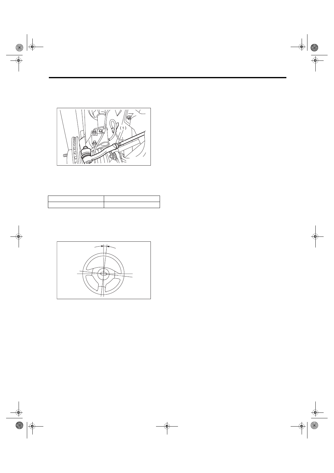
F: ADJUSTMENT
1) Adjust the front toe.
<Ref. to FS-12, FRONT WHEEL TOE-IN, INSPEC-
2) Check the steering angle of the wheels.
Standard of steering angle:
3) If the steering wheel spokes are not horizontal
when wheels are set in the straight ahead position,
or error is more than 5° on the periphery of the
steering wheel, correctly re-install the steering
wheel.
4) If the steering wheel spokes are not horizontal
with vehicle set in the straight ahead position after
this adjustment, correct it by turning the right and
left tie-rods in the opposite direction from each oth-
er by the same angle.
(1) Lock nut
Inner wheel
Outer wheel
36.6°±1.5°
32.2°±1.5°
(1) 5° or less
PS-00107
(1)
PS-00513
PS-39
Pipe Assembly
POWER ASSISTED SYSTEM (POWER STEERING)
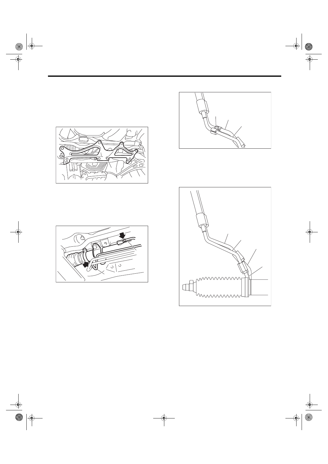
6. Pipe Assembly
A: REMOVAL
1) Disconnect the ground cable from battery.
2) Remove the under cover. <Ref. to EI-28, RE-
3) Lift up the vehicle, and remove the front cross-
member support plate.
4) Remove the one pipe joint at the center of the
gearbox, and connect the vinyl hose to the pipe and
the joint. Discharge the fluid by turning the steering
wheel fully clockwise and counterclockwise. Dis-
charge the fluid similarly from other pipes.
5) Remove the clamp E from return hose and pres-
sure hose.
6) Disconnect the return hose from return pipe and
disconnect the pressure hose from feed pipe.
7) Remove the air intake duct.
• Except for STI model: <Ref. to IN(w/o STI)-10,
• STI model: <Ref. to IN(STI)-10, REMOVAL, Air
(1) Front crossmember support plate
(1) Pipe A
(2) Pipe B
PS-00445
(1)
(2)
PS-00553
(1)
(1) Pressure hose
(2) Return hose
(3) Clamp E
(1) Feed pipe
(2) Return pipe
(3) Pressure hose
(4) Return hose
PS-00537
(3)
(1)
(2)
PS-00538
(4)
(3)
(2)
(1)
PS-40
Pipe Assembly
POWER ASSISTED SYSTEM (POWER STEERING)
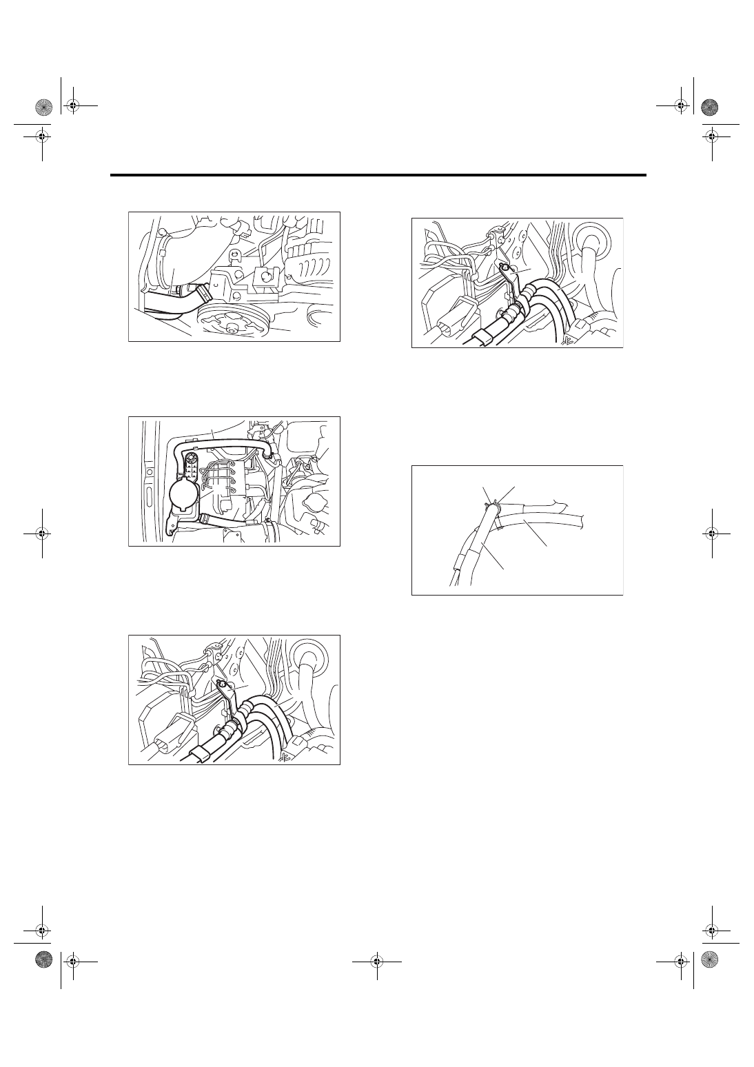
8) Disconnect the suction hose and pressure hose
from oil pump.
9) Disconnect the suction hose and return hose
from the reservoir tank.
10) Remove the hose bracket and take out the
hose assembly from vehicle.
B: INSTALLATION
1) Temporarily tighten the hose bracket bolt.
2) Install the plastic clip to the pressure hose and
suction hose.
CAUTION:
Align the installation position of the plastic clip
with the protector edge of the suction hose.
(1) Suction hose
(2) Pressure hose
(1) Reservoir tank
(2) Suction hose
(3) Return hose
(1) Hose ASSY
(2) Hose bracket
PS-00459
(2)
(1)
PS-00799
(3)
(1)
(2)
PS-00624
(2)
(1)
(1) Hose ASSY
(2) Hose bracket
(1) Plastic clip
(2) Protector
(3) Suction hose
(4) Pressure hose
PS-00624
(2)
(1)
PS-00456
(1)
(2)
(3)
(4)
Нет комментариевНе стесняйтесь поделиться с нами вашим ценным мнением.
Текст